background image

iDP-3221 Service Manual

– 

17

 –

CITIZEN

10. Removing the Thermal Head from the Control Board

(1) Insert a flat-blade screwdriver between the heat sink of the thermal head and head BK

(insert it into the place shown by the arrow) and, with weak force, lift the thermal head
from the connector until it floats from the connector a little.

(2) Lift the other end in the same way.
(3) Without touching the thermal elements, remove the thermal head from the connector

by lifting it upward.

Note: By performing above steps (1) to (3) after removing the upper cover, it is possible to

remove the thermal head without detaching the control board.

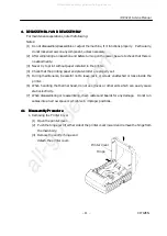
11. Removing the Motor from the Chassis

(1) Remove the upper cover.
(2) Remove the control board.
(3) Remove the motor cable

form the chassis and
detach the motor by
removing the two screws
(M3

´

5).

Motor

Thermal Head

Heat Sink

All manuals and user guides at all-guides.com

Summary of Contents for iDP-3221 Series

Page 1: ...n n C C C CB B B BM M M M C C C Co o o or r r rp p p po o o or r r ra a a at t t ti i i io o o on n n n I I I In n n nf f f fo o o or r r rm m m ma a a at t t ti i i io o o on n n n S S S Sy y y ys s...

Page 2: ...his manual thoroughly to understand its contents 1 Small lightweight with a small footprint 2 Designed with a reduced number of components to ensure low cost 3 Paper is added by simply placing the pap...

Page 3: ...sm 9 3 4 1 Drive Control Overview 9 3 4 2 Print Data and Print Positions 10 4 DISASSEMBLY AND REASSEMBLY 11 4 1 Disassembly Procedure 11 4 2 Reassembly Procedure 18 5 TROUBLESHOOTING 19 5 1 Troublesho...

Page 4: ...Control PCB Assy 3221 01 Serial Interface D sub 25 36 7 2 2 Control PCB Assy 3221 02 Parallel Interface 37 8 OUTER DIMENSION 38 For the auto cutter unit ACS 231 see the separate Service Manual All ma...

Page 5: ...I I IN N N NG G G G A A A AN N N ND D D D M M M MA A A AI I I IN N N NT T T TE E E EN N N NA A A AN N N NCE CE CE CE O O O OF F F F P P P PR R R RI I I IN N N NT T T TE E E ER R R R See the User s Man...

Page 6: ...DE 93 Paper Thermal paper roll 80 0 1 mm f83 max mm See Paper Specifications Interface Serial RS 232C Parallel IEEE 1284 compliant Bi directional communication Input buffer 4 KB or 72 bytes Selectable...

Page 7: ...s s s sm m m mi i i is s s ss s s si i i io o o on n n n a a a an n n nd d d d P P P Pa a a ap p p pe e e er r r r F F F Fe e e ee e e ed d d d M M M Me e e ec c c ch h h ha a a an n n ni i i is s s s...

Page 8: ...he chassis The movable end of each head spring can be released from the hook on the chassis to remove the platen roller 3 3 3 3 3 3 3 3 S S S Se e e en n n ns s s so o o or M r M r M r Me e e ec c c c...

Page 9: ...in this printer is a thermal head It consists of thermal elements and a head driver The thermal elements are driven and controlled by the head driver 3 3 3 3 4 4 4 4 1 1 1 1 D D D Dr r r ri i i iv v v...

Page 10: ...P P P Pr r r ri i i in n n nt t t t P P P Po o o os s s si i i it t t ti i i io o o on n n ns s s s The 512 bit print data numbers 1 512 transferred from DATA IN DI is printed at the posi tions shown...

Page 11: ...operly set 5 During maintenance be careful not to leave parts or screws unattached or loose inside the printer 6 When handling the thermal head do not use gloves or other aids which can easily cause s...

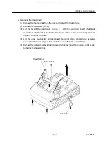
Page 12: ...into the slit at the front of the printer between the chassis and upper cover and to unlock the claws 4 Lift the upper cover gently and disconnect the connectors of sensors such as paper near end sen...

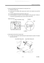
Page 13: ...tly disengage the PC board from the two projections of the upper cover to remove it In this case pay special attention so as not to break the projections 4 Removing the Rollers from the Upper Cover 1...

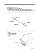
Page 14: ...then remove the platen bush platen lever L and E ring 6 Removing the Pressure Roller 1 Remove the printer cover 2 Remove the two screws M2 6 6 to detach the pressure roller block from the printer cov...

Page 15: ...while turning it in the direction Then the bottom plate comes off the chassis 8 Removing the Auto Cutter ACS 231 from the Chassis 1 Remove the bottom plate 2 Remove the upper cover 3 Disconnect the c...

Page 16: ...is not installed remove only the platen roller as it is unnecessary to remove the upper cover 3 Remove the two screws M3 16 and two screws M3 8 4 Remove the control board by lifting it upward In this...

Page 17: ...ther end in the same way 3 Without touching the thermal elements remove the thermal head from the connector by lifting it upward Note By performing above steps 1 to 3 after removing the upper cover it...

Page 18: ...ht and then remove them by lowering them 4 4 4 4 2 2 2 2 R R R Re e e ea a a as s s ss s s se e e em m m mb b b bl l l ly y y y P P P Pr r r ro o o oc c c ce e e ed d d du u u ur r r re e e e Reassemb...

Page 19: ...ed procedure you can troubleshoot ef ficiently with fewer misjudgments 5 5 5 5 2 2 2 2 T T T Tr r r ro o o ou u u ub b b bl l l le e e es s s sh h h hoo oo oo oot t t ti i i in n n ng g g g G G G Gu u...

Page 20: ...the specified paper Faulty thermal head unit Replace the thermal head unit Low DC output voltage from the AC adapter Check the DC voltage with a DC voltmeter Supply the specified AC voltage to the AC...

Page 21: ...nnection of the ther mal head Check any deformation or bending of the head spring Replace the deformed head spring Paper feed failure Check whether or not the paper is jamming or torn and caught in th...

Page 22: ...ces are adhered to the paper near end sensor Remove the foreign substance F F F Fa a a au u u ul l l lt t t ty y y y a a a au u u ut t t to o o o c c c cu u u utt tt tt tte e e er r r r Phenomenon Cau...

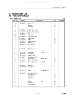
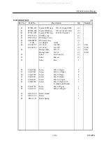
Page 23: ...8 E6601 330 Finger Guard 1 9 E62010730 Upper Cover Assy 1 10 E62010731 Upper Cover 1 11 E6612 050 Roller 2 12 E5200 250 Ope pane Sheet 1 13 E5049 030 PF Button 1 14 E6611 670 Sensor Guard 1 17 E62040...

Page 24: ...for 120V 1 USA E6100 730 AC Cord for 230V 1 EUR 49 Rating Label 3221 U 1 USA Rating Label 3221 E 1 EUR 52 Label Don t touch 2 1 53 Label Drawer 1 54 Label Hot 1 58 23G57459 Screw M2 3 S Tight 5 59 23...

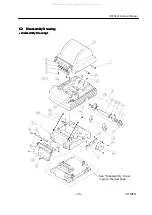
Page 25: ...m m mb b b bl l l ly y y y D D D Dr r r ra a a aw w w wi i i in n n ng g g g D D D Di i i is s s sa a a ass ss ss sse e e em m m mb b b bl l l ly y y y D D D Dr r r ra a a aw w w wi i i in n n ng g g...

Page 26: ...nual 26 CITIZEN D D D Di i i is s s sa a a ass ss ss sse e e em m m mb b b bl l l ly y y y D D D Dr r r ra a a aw w w wi i i in n n ng g g g 2 2 2 2 All manuals and user guides at all guides com a l l...

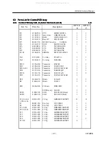
Page 27: ...10680 TTL SN74LS06NS 1 IC8 E2010670 TTL SN74LS07NS 1 IC102 E 104 690 EPROM M27C1001 45XF1 1 1 TA1 E390 290 Tr Array STA471A 1 1 TA2 E 202 830 Tr Array TA8428K 1 1 TR1 5 E 358 080 Transistor RN1302 2 2...

Page 28: ...410 C Resistor RK73K2A 33KW J 5 5 104 R8 14 101 E3900 420 C Resistor RK73K2A 180W J 3 3 R9 Resistor RSF2BC 2 7W J 1 1 R10 11 24 25 E3900 430 C Resistor RK73K2A 10KW J 7 7 27 107 108 R15 26 E3900 440...

Page 29: ...1 1 F2 E4005 770 Fuse MQ1 5 1 1 X1 E 501 360 X tal CSTCS16 00MX0C3 SOP or CST16 00MXW0C3 DIP 1 1 L1 2 14 21 E4009 480 Fe Beads BLM41P600S 10 10 L3 13 22 25 E4009 490 Fe Beads BLM21A121S 30 30 28 33 3...

Page 30: ...1 1 1 1 C C C Co o o on n n nt t t tr r r ro o o ol l l l P P P PCB CB CB CB A A A Ass ss ss ssy y y y 3221 3221 3221 3221 01 01 01 01 S S S Se e e er r r ri i i ia a a al l l l I I I In n n nt t t t...

Page 31: ...iDP 3221 Service Manual 31 CITIZEN S S S So o o ol l l ld d d de e e er r r r S S S Si i i id d d de e e e Keytop All manuals and user guides at all guides com a l l g u i d e s c o m...

Page 32: ...P P P PCB CB CB CB A A A Ass ss ss ssy y y y 3221 3221 3221 3221 02 02 02 02 P P P Pa a a ar r r ra a a al l l ll l l le e e el l l l I I I In n n nt t t te e e er r r rf f f fa a a ac c c ce e e e P...

Page 33: ...iDP 3221 Service Manual 33 CITIZEN S S S So o o ol l l ld d d de e e er r r r S S S Si i i id d d de e e e Keytop All manuals and user guides at all guides com...

Page 34: ...W WI I I IN N N NG G G G The following lists the reference drawings for maintenance and so on Block diagram Circuit diagrams for the following circuits Control PCB Assy Serial Interface Control PCB As...

Page 35: ...iDP 3221 Service Manual 35 CITIZEN 7 7 7 7 1 1 1 1 B B B Bl l l lo o o oc c c ck k k k D D D Di i i ia a a ag g g gr r r ra a a am m m m All manuals and user guides at all guides com...

Page 36: ...2 2 2 1 1 1 1 C C C Co o o on n n nt t t tr r r ro o o ol l l l P P P PCB CB CB CB A A A Ass ss ss ssy y y y 3221 3221 3221 3221 01 01 01 01 S S S Se e e er r r ri i i ia a a al l l l I I I In n n nt...

Page 37: ...n nt t t tr r r ro o o ol l l l P P P PCB CB CB CB A A A Ass ss ss ssy y y y 3221 3221 3221 3221 02 02 02 02 P P P Pa a a ar r r ra a a al l l ll l l le e e el l l l I I I In n n nt t t te e e er r r...

Page 38: ...l 38 CITIZEN 8 8 8 8 O O O OU U U UT T T TER ER ER ER D D D DI I I IM M M ME E E EN N N NS S S SI I I IO O O ON N N N P P P Pr r r ri i i in n n nt t t te e e er r r r Unit mm All manuals and user gui...

Page 39: ...iDP 3221 Service Manual 39 CITIZEN AC AC AC AC A A A Ad d d da a a ap p p pt t t te e e er r r r 31 31 31 31A A A AD D D D Unit mm All manuals and user guides at all guides com...

Reviews: