background image


– 47 –


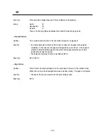
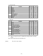
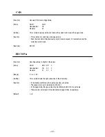
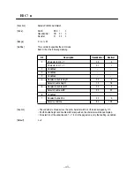
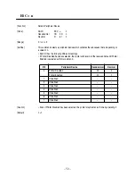
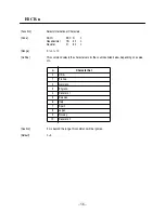
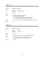
ESC & y c1 c2 [x[d]yxx]c2-c1+1


[Function]

Defines Download Characters

[Code]

ASCII

ESC &

y

c1

c2

[x [d] y 


×


 x ] c2-c1+1

Hexadecimal

1B

26

y

c1

c2

[x [d] y 


×

 x ] c2-c1+1

Decimal

27

38

y

c1

c2

[x [d] y 

×

 x ] c2-c1+1

[Range]

y = 1
32 


c1 


c2 


126


6 (When the 5 

×

 7 font is selected)


10 (When the 7 

×

 7 font is selected)


d1 ... d y 

×

 x 


255 

[Outline]

This command defines the font of the alphanumeric or Kana download characters.
• y denotes the number of vertical bytes.
• c1 denotes the start character code and c2, end character code, respectively.  When defining 

only one character, set c1 = c2.

• The definable character code is the 95 ASCII code characters from <20>H to <7E>H.
• x denotes the number of horizontal dots to be defined.
• d denotes the data to be defined; a horizontal x dots pattern from the left.  The right 

remaining pattern results in spaces.

[Caution]

• Once the download characters are defined, they will remain valid until they are redefined, 

ESC @ is executed, the printer is reset, or the power is turned off.

• If y, c1, c2, or x is beyond the range, this command will be ignored, processing the 

subsequent data as normal one.

• In case of the 7 

×

 7 font, define the data so that the horizontally adjacent dots will not be 

contained, because they cannot be printed.

[Default]

Identical pattern with the internal character set

[See Also]

ESC %

Summary of Contents for CBM-820

Page 1: ...TERMINAL SLIP PRINTER MODEL CBM 820 User s Manual...

Page 2: ......

Page 3: ...Loading is a trademark of Star Micronics Co Ltd Windows codepage is a registered trademark of Microsoft Corporation Declaration of Conformity This printer conforms to the following Standards Low Volta...

Page 4: ...ion cord ampere rating Also make sure that the total of all products plugged into the wall outlet does not exceed 15 amperes Never push objects of any kind into this product through cabinet slots as t...

Page 5: ...kabel mu der Stromst rke aller daran angeschlossenen Ger te entsprechen Keine Gegenst nde in die Geh useschlitze schieben Drucker darf nur da gewartet werden wo im Handbuch angegeben ffnen und Abnehme...

Page 6: ...ser at his own expense will be required to take whatever measures may be necessary to correct the interference CAUTION Use shielded cable for this equipment Sicherheitshinweis Die Steckdose zum Anschl...

Page 7: ...operation handling or an improper operating environment 6 Operate the equipment only as described in this User s Manual otherwise accidents or problems may result 7 Data are basically temporary they...

Page 8: ...d damages that can occur if the given instructions are neglected or the equipment is incorrectly operated WARNING Negligence of this precaution may result in death or serious injury CAUTION Negligence...

Page 9: ...o the cables Do not drop or insert any foreign substances such as clips or pins into the equipment Do not spill any liquid or spray any chemical containing liquid over the equipment If any liquid is s...

Page 10: ...use trouble or smoke fire Confirm that a plug socket used for connection has sufficient capacity Avoid connecting a power cable to a plug socket shared by other devices or extending the wiring too far...

Page 11: ...per could deteriorate the print quality or cause a problem with the printing head To Prevent Injury and Spreading of Damage Never touch the printing head motor or paper cutting blade Your finger may b...

Page 12: ...oth in water and wring it for wiping off the soil Never use organic solvents such as alcohol thinner trichlene benzene ketone or chemical dusters If the equipment is contaminated with paper powder use...

Page 13: ...3 4 6 Connecting to a peripheral unit 15 4 7 Inserting the paper into the printer 16 4 8 AutoSide Loading 17 4 9 Control Panel Operations 19 4 9 1 Indicator lights 19 4 9 2 Buttons 19 4 9 3 Producing...

Page 14: ...Schutzmaterialien 98 2 Technische Daten 99 2 1 Allgemeine Daten 99 2 2 Druckspezifikationen 100 2 3 Papier Spezifikationen und Druckbereich 100 2 4 Technische Daten zur Netzversorgung 102 3 Au enansic...

Page 15: ...are DIP Schaltereinstellungen 122 5 3 Einstellen der Speicherschalter 123 6 Schnittstelle 124 6 1 Stifte und Signalnamen 124 6 2 Schnittstellenanschl sse 125 7 Treiberschaltung f r periphere Einheiten...

Page 16: ...nter will not be exposed to vibration The power outlet you plan to connect to for power should be nearby and unobstructed Make sure that the printer is close enough to your host computer for you to co...

Page 17: ...ng is missing contact the dealer where you bought the printer and ask them to supply the missing part Note that it is a good idea to keep the original box and all the packing materials just in case yo...

Page 18: ...rotective materials Four protective materials are inserted into the printer to protect components during shipping Before using the printer be sure to remove all protective materials as shown in the il...

Page 19: ...Serial RS 232C standard Data Buffer 2 K bytes 35 bytes Can be selected by DIP switch Reliability Mechanism MCBF 2 5 million lines Printer head life 70 million characters Operating Environment Temperat...

Page 20: ...or 2 ply forms to 0 25 mm 0 0047 to 0 0098 Maximum 0 2 mm when printing graphics Copy Offset 1 5mm maximum 15 lines between top sheet and bottom sheet Binding Top or left Print Area Distance from firs...

Page 21: ...sensor to erroneously report an out of paper condition Paper Feed Drive Stepping motor Pitch Adjustable in n 60 units approximate Speed while printing 3 5 per second Speed while ejecting 4 5 per secon...

Page 22: ...to protect against electrostatic AC line noise etc Power Supply AC Adaptor 31AD switching type Input AC100 to 240V 50 60Hz Output DC 24V 5 1 9A Plug TCP8927 83 1100 Hoshiden brand or equivalent Consum...

Page 23: ...ches provide control over printer functions Power switch Turns printer power on and off Document table Supports the paper fed into the printer For connection to a host computer For connection of the A...

Page 24: ...Installing the ribbon cassette Make sure that the printer s paper release is activated the paper is not held in place by the paper feed roller If it cannot be determined whether or not the paper relea...

Page 25: ...any slack in the ribbon Holding the ribbon cassette so that the ribbon is facing down install the cassette into the slip printer as shown in the illustration Press gently but firmly on the cassette u...

Page 26: ...tly pull it away from the printing mechanism Use the procedure under Installing the ribbon cassette on page 9 to install a new cassette 4 4 Connecting to a power outlet and turning power on and off Ma...

Page 27: ...mend that you unplug the printer from the power outlet whenever you do not plan to use it for long periods Because of this you should locate the printer so that the power outlet it is plugged into is...

Page 28: ...interface cable that is used with an IBM compatible personal computer Note that they do not apply to all types of computers and cables If you are unsure about what type of cable you should use to con...

Page 29: ...ock it Use scissors to cut off any excess Plug one end of the serial cable into the serial port of your computer and the other end of the cable into the socket on the back of the printer Secure both c...

Page 30: ...is required Note that this printer does not come with a modular plug or wire so it is up to you to obtain one that suits your needs Important Make sure that the printer is turned off and unplugged fro...

Page 31: ...of paper or it could cause malfunction or damage of the printer The following procedure describes how to print on paper Before trying to print be sure to install a ribbon cassette into the printer usi...

Page 32: ...use of this it is recommended that you always insert paper from the side 4 8 AutoSide Loading This printer is equipped with paper sensors so you do not have to perform any special procedure to align t...

Page 33: ...t that time the PAPER OUT indicator will go out and the printer mechanism will automatically align the paper for printing from the top Send data from your host computer to be printed on the paper Afte...

Page 34: ...Light Off On Flashing POWER Power off Power on Dot Alignment Adjust Mode PAPER OUT Paper inserted No paper Insert paper prompt RELEASE Slip paper engaged Slip paper released Mechanical error Button De...

Page 35: ...a few moments until the printer beeps and the printer test print starts The printer test will continue until it reaches the end of the paper 4 9 4 Adjusting the dot alignment You may never have to use...

Page 36: ...dicator by a flashing POWER indicator flashes Entering the Dot Alignment Adjust Mode causes seven blocks to be printed each of which indicates a dot alignment setting as shown below An asterisk to the...

Page 37: ...elled 4 9 5 Hexadecimal dump This procedure prints in hexadecimal format all codes character codes and control codes that are sent to the printer by the computer The printer does not execute any contr...

Page 38: ...to recover from a data receive error depends on the current command mode ErrorType Indicators Recovery POWER RELEASE PAPER OUT Paper jam Flashing Correct the cause of the problem and then press RELEAS...

Page 39: ...distance between print head pin 9 and the trailing edge of the paper becomes 27 3 mm or less When the auto clamp is enabled with Memory Switch 5 1 the auto clamp operation is performed about 1 0 seco...

Page 40: ...he DIP switches are located inside the printer underneath the document table Use the following procedure to remove the document table so you can operate the DIP switches Make sure that the printer is...

Page 41: ...e document table can slide freely After the document table is opened sufficiently use a thin flat blade screwdriver or some other similar object to change DIP switch settings Note See the following se...

Page 42: ...r ON OFF 1 Baud Rate See table below 2 3 Data Length 8 bits 7 bits 4 Parity Check Disabled Enabled 5 Parity Odd Even 6 Handshake DTR DSR XON XOFF 7 Receive Buffer Size 2K bytes 35 bytes 8 Character Co...

Page 43: ...the functions and settings of memory switches see the 9 Print Control Functions ESC The table below shows the factory settings for the memory switches Warning Changing the memory switch settings can c...

Page 44: ...gnal 5 N C Not connected 6 DSR IN DIP Switch 9 OFF In DTR DSR communication mode when Memory Switch4 5 0 indicates whether data receive from host is enabled or disabled Space Receive enabled Mark Rece...

Page 45: ...space except during following conditions Period between reset and communication enabled During self test printing and dot alignment adjustment 21 24 N C Not connected 25 INIT IN DIP Switch 10 OFF Thi...

Page 46: ...ral unit is located on the back of the printer To connect to the drive circuit connect the peripheral unit to the modular connector using a cable supplied by you like that one shown in the figure belo...

Page 47: ...is 24 Absolute maximum ratings for diodes D1 and D2 Ta 25 C are Average Rectified Current Io 1A Maximum forward surge current 60Hz 1 cycle sine wave IFSM 40A Absolute maximum rating for transistors TR...

Page 48: ...33 8 Maintenance and Service For the information on maintenance and service please contact our dealer...

Page 49: ...mmand 1BH 23H N n1 n2 n3 n4 44 ESC Selects Deselects Download Character Set 1BH 25H n 46 ESC Defines Download Characters 1BH 26H y c1 c2 47 ESC Selects Bit Image Mode 1BH 2AH m 49 ESC 2 Sets 1 6 inch...

Page 50: ...64H n 62 ESC e Print and N line Reverse Paper Feed 1BH 65H n Disabled 63 ESC f Sets Single Sheet Waiting Time 1BH 66H t1 t2 63 ESC p Generates Specified Pulses 1BH 70H m t1 t2 64 ESC q Release 1BH 71H...

Page 51: ...ion Code Shows a sequence of code consisting the command ASCII represents the ASCII code and k a repeat count of k times Range Shows a settable range of an argument Outline Outlines the command Cautio...

Page 52: ...ed if the next horizontal tab position has not been set Initial setting of the horizontal tab position is every 8 characters of the 5 7 font 9th 17th 25th character and so on See Also ESC D Function L...

Page 53: ...jected completely If it has been set the paper will be ejected by a set amount If the no paper condition is detected halfway ejection the printer will stop paper ejection even before reaching the set...

Page 54: ...n a data sequence of 10 H 04 H n 1 n 3 n 5 is received other than this command Example d1 10 H d2 04 H d3 1 in ESC m nL nH d nL 256 nH This command must not be used by interrupting the code sequence o...

Page 55: ...kick connector No 3 pin L 00 0 Status of the drawer kick connector No 3 pin H 04 4 3 On line status 00 0 Off line status 08 8 4 Unused 10 16 5 Undefined 6 Undefined 7 Unused 00 0 Bit Description Hexad...

Page 56: ...3 Undefined 4 Unused 10 16 5 No irrecoverable error 00 0 Irrecoverable error 20 32 6 Undefined 7 Unused 00 0 Bit Description Hexadecimal Decimal 0 Unused 00 0 1 Unused 02 2 2 The slip has been select...

Page 57: ...s extended over the currently set print area See Also ESC W Function Sets Space Size to Right of Characters Code ASCII ESC SP n Hexadecimal 1B 20 n Decimal 27 32 n Range 0 n 32 Outline This command se...

Page 58: ...both double height and double width are specified the characters will be quadrupled For selection of the underline and 7 7 font in the page mode only their setting is enabled Default n 0 Bit Descripti...

Page 59: ...e power again or reset with the following reset command to enable setting If reset with the command self printing will be implemented Reset command ESC CAN LF NUL Caution The EEROM has a data writing...

Page 60: ...e Table below B n2 A 9 LSB 8 7 n3 6 5 LSB 4 3 n4 2 1 Automatic clamp function Enabled Disabled LSB 0 Automatic head search function Enabled Disabled MSW5 D MSW5 C ESC q Command Function 0 0 Implements...

Page 61: ...37 n Range 0 n 255 Outline This command selects or deselects the download character set n is valid only for the least significant bit At n 0 B the command deselects the download character set selects...

Page 62: ...c1 c2 The definable character code is the 95 ASCII code characters from 20 H to 7E H x denotes the number of horizontal dots to be defined d denotes the data to be defined a horizontal x dots pattern...

Page 63: ...SB When defining the pattern above to the code 20H ESC y c1 c2 x p1 p2 p3 p4 p5 Code hex 1B 26 01 20 20 05 3E 48 88 48 3E p1 p2 p3 p4 p5 p6 p7 p8 p9 p10 MSB LSB When defining the pattern above to the...

Page 64: ...1 in the corresponding bit when printing and 0 when not printing The following table lists the bit image mode selected with m Caution If a value of m or nH goes beyond the range this command will be i...

Page 65: ...50 The following shows the relations between the bit image data and the dots printed 7 6 5 4 3 2 1 0 Bit Image Data High Low Print Data...

Page 66: ...e Feed Amount Code ASCII ESC 3 n Hexadecimal 1B 33 n Decimal 27 51 n Range 0 n 255 Outline This command sets a line feed amount per line to n 60 inch Caution There are two kinds of set values for the...

Page 67: ...wing different meanings If Printer Disabled has been selected the printer will discard all the received data until Printer Enabled is selected with this command Caution Even if Printer Disabled has be...

Page 68: ...ception buffer is not cleared Function Sets Single Sheet Ejection Length Code ASCII ESC C n Hexadecimal 1B 43 Decimal 27 67 Range 0 n 127 Outline This command sets a single sheet ejection length to n...

Page 69: ...which denotes a setting position is input in the ascending order and ends with 00 H ESC D NUL clears all the set tab positions After clearing HT is ignored Caution If the data n k is equal to or smal...

Page 70: ...nal ejection selects forward directional ejection Default n 0 See Also FF Function Print and Paper Feed Code ASCII ESC J n Hexadecimal 1B 4A n Decimal 27 74 n Range 0 n 255 Outline This command prints...

Page 71: ...0 inch in the reverse direction Since the printer has the minimum paper feed pitch of 1 144 inch n 60 inch reverse directional paper feed is treated as follows For the standard mode The paper is fed b...

Page 72: ...ting in increments of half dot in the standard mode Only the font consisting of normal dots is valid The following commands have two kinds of set values for the standard mode and page mode ESC SP Sets...

Page 73: ...nge 0 n 10 Outline This command selects the character sets for the countries listed below depending on a value of n Caution If n is beyond the range this command will be ignored Default n 0 n Characte...

Page 74: ...n 0 48 Start point at upper left A n 1 49 Start point at lower left B n 2 50 Start point at lower right C n 3 51 Start point at upper right D Caution If the printing direction is specified or changed...

Page 75: ...eyond the printable area on the paper is automatically adjusted to the maximum settable area based on the effective values from xL to dyH i e xL xH yL yH dxL dxH dyL and dyH The maximum x directional...

Page 76: ...g stop condition but if any one of them detects the no paper condition the printer will stop printing The printer stops printing after printing the on going line and feeding the paper If the panel swi...

Page 77: ...ommand disables the panel switch Caution If the panel switch is disabled with this command all the panel switches will be disabled Default n 0 Function Print and N line Paper Feed Code ASCII ESC d n H...

Page 78: ...osition The set amount does not remain Function Sets Single Sheet Waiting Time Code ASCII ESC f t1 t2 Hexadecimal 1B 66 t1 t2 Decimal 27 102 t1 t2 Range t1 0 0 t2 64 Outline This command sets the time...

Page 79: ...ed with t1 or t2 to the connector pin m The following table lists the types of m The ON time shall be t1 2 mS and OFF time t2 2 mS respectively Caution If m goes beyond the range this command will be...

Page 80: ...n Caution If the panel switch is disabled and the no paper sensor valid for print stop detects the no paper condition the printer will execute a release regardless of this command This command is vali...

Page 81: ...3 The ROM version can be confirmed in a test print For the test print operating method see 4 9 3 Producing a test print Default n 0 See Also 10 Character Codes Table n CharacterType 0 Codepage PC437 U...

Page 82: ...be ready to receive If XON XOFF control is selected or the memory switch 4 5 is set to 1 the printer will send only 1 byte without confirming the DSR signal status Since this command is executed at d...

Page 83: ...t confirming the DSR signal status If printing is under way the printer will sends the then status after printing that line and feeding the paper the status sending timing differs from ESC u and GS I...

Page 84: ...n 0 B the command deselects inverted print At n 1 B the command selects inverted print Caution Inverted print refers to turning the line by 180 degrees to print it upside down The command is valid onl...

Page 85: ...l send only 1 byte without confirming the DSR signal status Since this command is executed at deployment of the reception buffer there may be a delay between command reception and status sending depen...

Page 86: ...tus The 4 byte status to be sent must be always successive except the XOFF code Since this command is executed at deployment of the reception buffer there may be a delay between command reception and...

Page 87: ...the paper by the Paper Feed switch 00 0 Feeding the paper by the Paper Feed switch 40 64 7 Unused 00 0 Bit Status Hexadecimal Decimal 0 Undefined 1 Undefined 2 Undefined 3 Undefined 4 Unused 00 0 5 N...

Page 88: ...en the slip is inserted and 1 unprintable when ejection starts If the printer is waiting for insertion of the slip The bits 5 and 6 of the 3rd byte will be turned to 1 no paper and the bit 1 of the 4t...

Page 89: ...to 1 the printer will send 1 byte without confirming the DSR signal status Since this command is executed at deployment of the reception buffer there may be a delay between command reception and statu...

Page 90: ...us Hexadecimal Decimal 0 Drawer kick connector No 3 pin status L 00 0 Drawer kick connector No 3 pin status H 01 1 1 Undefined 2 Undefined 3 Undefined 4 Unused 00 0 5 undefined 6 Undefined 7 Unused 00...

Page 91: ...76 10 Character Codes Table 10 1 Codepage PC437 USA European Standard...

Page 92: ...77 10 2 Codepage Katakana Japanese...

Page 93: ...78 10 3 Codepage PC850 Multilingual...

Page 94: ...79 10 4 Codepage PC860 Portuguese...

Page 95: ...80 10 5 Codepage PC863 Canadian French...

Page 96: ...81 10 6 Codepage PC865 Nordic...

Page 97: ...82 10 7 Codepage PC852 Eastern Europe...

Page 98: ...83 10 8 Codepage PC866 Russian...

Page 99: ...84 10 9 Codepage PC857 Turkish...

Page 100: ...85 10 10 Windows Codepage...

Page 101: ...86 10 11 Codepage PC858 Multilingual Euro...

Page 102: ...87 Appendix 1 Outline Drawing of Printer CBM 820 Dimensions and Weight Dimensions 180 W 190 D 138 H mm 7 09 7 48 5 43 Weight 2 1 kg 4 6 lbs 180 mm 7 09 138 mm 5 43 190 mm 7 48...

Page 103: ...88 Appendix 2 Outline Drawing of AC Adapter 31AD Dimensions and Weight Dimensions 70 W 130 D 40 H mm 2 76 5 12 1 58 Weight 0 43 kg 0 94 lbs 40 70 AC ADAPTER 1500 100 10 Unit mm 3 130 1 5mm MAX...

Page 104: ...German...

Page 105: ...enung falsche Handhabung oder eine ungeeignete Betriebsumgebung zur ckzuf hren sind 6 Zur Vermeidung von Unf llen und sonstigen Problemen ist das Ger t ausschlie lich auf die in der Bedienungsanleitun...

Page 106: ...urch eine Mi achtung der Bedienungshinweise oder durch die unsachgem e Handhabung des Ger ts entstehen k nnen WARNUNG Die Mi achtung dieser Vorsichtsma regel kann zu K rperverlet zungen mit m glicher...

Page 107: ...ern in das Ger t gelangen Darauf achten keine Fl ssigkeiten auf dem Ger t zu vergie en oder chemische Substanzen enthaltende Sprays dar ber zu verspr hen Bei versehentlichem Na werden das Ger t sofort...

Page 108: ...ie lich mit der vorgeschriebenen Netzspannung betreiben Eine Mi achtung dieser Vorsichtsma regel kann Br nde elektrische Schl ge und Funktionsst rungen verursachen Vergewissern da die f r den Anschlu...

Page 109: ...e Papier verwenden Durch Verwendung anderer Papiersorten kann die Druckqualit t beeintr chtigt oder Probleme mit dem Druckkopf verursacht werden Zur Vermeidung von Verletzungen und Sch den Niemals den...

Page 110: ...euchten auswringen und damit abwischen Hierzu niemals fl chtige organische L sungsmittel wie z B Alkohol Terpentin Trichlorethan Benzol Keton oder chemische Staubentfernungsmittel verwenden Papierstau...

Page 111: ...sten Untergrund aufstellen wo keine Vibrationen vorhanden sind Die verwendete Steckdose soll in der N he und frei zug nglich sein Sicherstellen da der Drucker nahe genug am Computer ist um die Ger te...

Page 112: ...n Falls Teile fehlen wenden Sie sich zwecks Nachlieferung bitte an den Fachhandel bei dem das Ger t gekauft wurde Im Hinblick auf einen eventuellen zuk nftigen Transport des Druckers empfiehlt es sich...

Page 113: ...chutzstreifen und ein St ck Pappe sind im Drucker eingelegt um die internen Bauteile beim Transport zu sch tzen Vor der Inbetriebnahme des Druckers m ssen die in der Abbildung markierten Schutzmateria...

Page 114: ...lle RS 232C Standard Datenpuffer 2KB 35 Bytes Kann mit DIP Schalter gew hlt werden Zuverl ssigkeit Mechanismus MCBF 2 5 Millionen Zeilen Lebensdauer des Druckkopfes 70 Millionen Zeichen Betriebsumgebu...

Page 115: ...erschiebung Maximal 1 5 mm 15 Zeilen zwischen oberem und unterem Blatt Binden Oben oder links Druckbereich Abstand von der ersten Druckzeile Kopf Nr 1 bis zur oberen Papierkante Blattanschlag 28 6 mm...

Page 116: ...s verursachen Papiervorschub Antrieb Schrittmotor Abstand In Einheiten von ca n 60 Zoll einstellbar Geschwindigkeit w hrend des Druckbetriebs 3 5 Zoll s Geschwindigkeit w hrend des Druckbetriebs 4 5 Z...

Page 117: ...elektrostatisches Netzleitungsrauschen usw zu treffen Netzversorgung Netzteil 31AD Schalttyp Eingang 100 bis 240 V Netzspannung 50 60 Hz Ausgang DC 24V Gleichspannung 5 1 9 A Stecker TCP8927 83 1100...

Page 118: ...usschalten des Druckers Dokumentenauflage St tzt das Quittungspapier das in den Quittungsdrucker eingeschoben wird Schnittstellenbuchse Zum Anschlie en an den Hostcomputer Netzteil Anschlu buchse Zum...

Page 119: ...a die Papierfreigabe des Druckers aktiviert ist das Papier wird nicht von der Papier Zufuhrrolle festgehalten Sollten Sie nicht feststellen k nnen ob die Papierfreigabe aktiv ist schalten Sie den Druc...

Page 120: ...schlaufen aufzuwickeln Die Farbbandkassette so halten da das Farbband nach unten weist und die Kassette in den Drucker einsetzen wie in der Abbildung gezeigt Die Farbbandkassette sanft aber fest herun...

Page 121: ...aus dem Druckmechanismus ziehen Die unter Einsetzen der Farbbandkassette auf Seite 60 beschriebenen Schritte ausf hren 4 4 Anschlu an eine Netzsteckdose und Ein Ausschalten der Netzversorgung Sicherst...

Page 122: ...aus der Steckdose zu ziehen wenn der Drucker l ngere Zeit lang nicht benutzt werden soll Der Drucker sollte vorzugsweise an einem Platz aufgestellt werden der leichten Zugang zur Netzsteckdose gew hrt...

Page 123: ...BM kompatiblen Personalcomputern verwendete Schnittstellenkabel Beachten Sie da die hier gegebenen Anweisungen nicht f r alle Computer und Kabel zutreffen Wenden Sie sich bitte an Ihren Fachh ndler fa...

Page 124: ...Schneiden Sie bersch ssiges Band mit einer Schere ab Ein Ende des Kabels an den seriellen Anschlu des Computers anschlie en und das andere Ende an die Buchse an der R ckseite des Druckers an Wenn die...

Page 125: ...dazu erforderlich ist Beachten Sie da der Drucker nicht mit einem Modularstecker oder Kabel ausgestattet ist Diese Teile m ssen vom Anwender besorgt werden Wichtig Vor dem Anschlie en der Kabel sicher...

Page 126: ...ers die Folge sein Die folgende Beschreibung zeigt Ihnen das Einlegen des Papiers in den Drucker Bevor Sie zu drucken beginnen pr fen Sie ob eine Farbbandkassette in den Drucker eingelegt ist Sollte d...

Page 127: ...r Seite eingelegt wird 4 8 Automatischer Papiereinzug AutoSide Loading Dieser Drucker ist mit einem Papiersensor ausgestattet so da Sie keine besonderen Prozeduren durchf hren m ssen um den Startpunkt...

Page 128: ...ge PAPER OUT ausgehen und der Druckermechanismus zieht das Blatt automatisch ein und richtet es an der Druckstartposition aus Senden Sie die Druckdaten die auf dieses Blatt gedruckt werden sollen von...

Page 129: ...geleuchten Die folgende Tabelle stellt die Bedeutung des Leuchtens Nichtleuchtens oder Blinkens der Anzeigeleuchten dar Anzeigeleuchte Aus Ein Blinkt POWER Ausgeschaltet Eingeschaltet Punktausrichtung...

Page 130: ...4 Einstellen der Punktausrichtung Das hier beschriebene Verfahren wird nur selten n tig Es kann aber vorkommen da nach l ngerem Gebrauch des Druckers die Punkte einzelner Grafiken nicht mehr richtig...

Page 131: ...richtung zu schalten Die Betriebsart wird durch das Blinken der POWER Anzeige angezeigt Wenn der Punktjustierung Modus eingeschaltet wird werden sieben Zeichenbl cke ausgedruckt wie unten gezeigt Ein...

Page 132: ...Bei diesem Verfahren werden alle Codes Zeichencodes und Steuercodes die vom Computer zum Drucker gesandt werden in sedezimaler Form ausgedruckt Der Drucker f hrt dabei keine Steuercodes aus wie etwa...

Page 133: ...en der Daten versucht zu beheben ist davon abh ngig in welchen aktuellen Befehlsmodus der Drucker geschaltet ist Fehlertyp Anzeigen Behebung POWER RELEASE PAPER OUT Papierstau Blinkt Die Ursache des P...

Page 134: ...uckkopfstift Nr 9 und Hinterkante des Papiers 27 3 mm oder weniger ist Wenn Auto Festspannnen mit dem Memory Schalter 5 1 aktiviert ist wird der Auto Festspannen Vorgang etwa 1 0 Sekunden Anfangswert...

Page 135: ...e DIP Schalter befinden sich im Drucker unter der Papierauflage F r Zugang zu den DIP Schaltern ist die Papierauflage wie folgt zu verschieben Vergewissern da der Drucker ausgeschaltet und der Netzste...

Page 136: ...ch sich die Ablage ungehindert verschieben l t Nach dem Aufschieben der Papierablage die DIP Schalter mit einem Flachendschraubendreher oder dergleichen wie ben tigt einstellen Hinweis Einzelheiten zu...

Page 137: ...ON OFF 1 Baudrate Siehe untenstehende Tabelle 2 3 Datenl nge 8 bits 7 bits 4 Parit tspr fung Inaktiv Aktiv 5 Parit t Ungerade Gerade 6 Quittungsaustausch DTR DSR XON XOFF 7 Empfangspuffergr e 2 K byt...

Page 138: ...r Funktionen und Einstellungen der Speicherschalter siehe 9 Print Control Functions ESC Die untenstehende Tabelle zeigt die werksseitigen Einstellungen der Speicherschalter Wichtig Ein Umstellen der S...

Page 139: ...schlossen 6 DSR IN DIP Schalter 9 OFF Speicherschalter 4 5 im DTR DSR Datenaustauschmodus 0 zeigt an ob der Datenempfang vom Hauptrechner aktiv oder inaktiv ist SPACE Empfang aktiviert MARK Empfang de...

Page 140: ...nd Wenn der Punkt zwischen R ckstellung und Datenaustausch aktiv ist W hrend des Selbsttestdrucks oder der Punktausrichtung 21 24 N C Nicht angeschlossen 25 INIT IN DIP Schalter 10 OFF Dieses Signal w...

Page 141: ...Anschlu peripherer Einheiten Zum Anschlu an die Treiberschaltung ist die periphere Einheit mit einem im Fachhandel erh ltlichen Kabel siehe Abbildung unten an den modularen Stecker anzuschlie en Wich...

Page 142: ...rt verf gbar Mindestwiderstand f r die Spulen L1 und L2 24 Absolute H chstnennwerte f r die Dioden D1 und D2 Ta 25 C durchschnittlicher Richtstrom Io 1 A Maximaler Vorw rtsstromsto 60 Hz 1 Zyklus Sinu...

Page 143: ...128 8 Wartung und Dienst F r Informationen ber Wartung und Kundendienst wenden Sie sich bitte an unseren H ndler...

Page 144: ...1 09E 0605 Printed in Japan...

Reviews: