3-48
Cisco UCS C460 Server Installation and Service Guide
OL-22326-01
Chapter 3 Maintaining the Server
Installing or Replacing Server Components
Step 2
Install adapters on the GPU card to prepare for installation:
a.
Remove the default rear-panel faceplate from the rear end of a new card. Remove the two securing
screws and set them aside.
b.
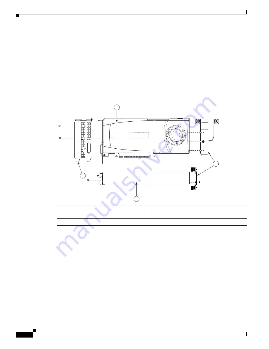
Install the new rear-panel faceplate to the rear end of the card (see
Figure 3-31
). Install the two
securing screws that you removed in the prior step.
c.
Install the front bracket to the front end of the card (see
Figure 3-31
). Insert the pins on the bracket
into the corresponding holes in the card and then tighten the single securing thumbscrew.
d.
Connect the power cable adapter to the card. Insert the six-pin connector on the cable into the six-pin
connector on the front end of the card.
Figure 3-31
Assembling Cisco C2050 GPU Card Components
Step 3
Install a new GPU card to the server:
a.
Align the card so that its bottom-edge connector is over PCIe slot 5.
b.
Tilt the front end of the card downward as you lower it into the chassis so that the attached power
cable goes under the CPU cage (behind CPU3). The two thumbscrews on the front bracket that you
installed must align with the two threaded holes in the CPU cage (see
Figure 3-32
).
c.
Perform the following two actions simultaneously:
–
Insert the two tabs on the rear-panel faceplate of the card into the two chassis rear-panel
openings for slots 5 and 6.
–
Carefully push down on both ends of the card to seat its connector in the PCIe slot 5
motherboard connector.
d.
Close the two green PCIe retainer latches for slots 5 and 6 over the top of the rear-panel faceplate.
e.
Tighten the two thumbscrews on the front bracket of the card to secure it to the CPU cage.
33
07
3
7
3
2
1
4
1
Rear-panel faceplate with two securing
screws
3
Front bracket
2
GPU card, side view
4
GPU card, top view


