3-6
Cisco uBR905 Router Hardware Installation Guide
OL-0598-01 (9/2000)
Chapter 3
Installing the Cisco uBR905 Router
Connecting Power
•
Use a crossover Ethernet cable to connect the Cisco uBR905 cable access router to an Ethernet hub
if more than four PCs or other LAN devices are to be connected at the site. Connect all devices to
the hub using straight-through Ethernet cables. (If your hub has an uplink port, you might be able
to use a straight-through cable to connect the hub directly to the computer.)
Step 2
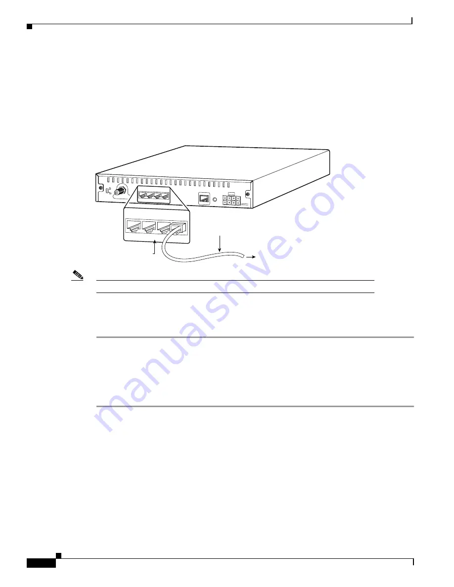
Connect one end of the Ethernet cable to one of the router’s Ethernet ports (labeled 1, 2, 3, or 4) at the
rear of the unit. (See Figure 3-2.)
Figure 3-2
Connecting the Ethernet Cable to the Cisco uBR905 Cable Access Router
Note
Do not connect the Ethernet cables into the RJ-45 console connector.
Step 3
Press the cable end firmly into the router’s Ethernet receptacle and connect the other end to the
computer or hub as applicable.
Step 4
Repeat Step 2 and Step 3 for each Ethernet connection from the Cisco uBR905 cable access router.
Connecting Power
To connect AC-input power to the Cisco uBR905 router:
Step 1
Locate the power receptacle at the rear of the cable access router. (Refer to the “Verifying Power
Requirements” section on page 3-3 to verify that this power source is adequate for the router.)
Step 2
Plug the 8-pin end of the AC power supply cord into the power connector at the rear of the router.
(See Figure 3-3.)
Cable TV In
Reset
Console
X
Ethernet 0
X
X
X
1
2
3
4
Cisco uBR924
To computer
35566
X
Ethernet 0
X
X
X
1
2
3
4
Ethernet 10BaseT
(RJ-45)
Ethernet cable
Power
5V


