background image

Getting Started with the Configuration Utility

Using the Configuration Utility

Services Ready Platform SRP 500 Series Administration Guide

16

2


NOTE

If you log in as cisco (with password of cisco), the Setup Wizard will automatically 
begin. if you log in as admin, you can start the Setup Wizard by clicking the 
Administration > Setup Wizard command.

STEP  4

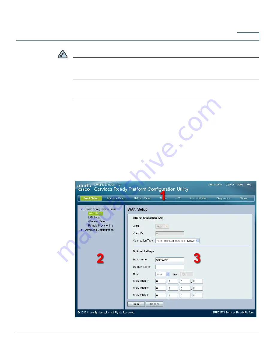
Click Log In. The Services Ready Platform Configuration Utility opens.

Using the Configuration Utility

Main Window Areas

The Configuration Utility is a web-based device manager that is used to provision 
the Services Ready Platform. You must have IP connectivity between the PC and 
the Services Ready Platform to configure it.

Summary of Contents for SRP 526W

Page 1: ...Cisco Small Business Pro Services Ready Platform SRP 500 Series ADMINISTRATION GUIDE ...

Page 2: ...ress Cisco Systems Cisco Systems Capital the Cisco Systems logo Cisco Unity Collaboration Without Limitation EtherFast EtherSwitch Event Center Fast Step Follow Me Browsing FormShare GigaDrive HomeLink Internet Quotient IOS iPhone iQuick Study IronPort the IronPort logo LightStream Linksys MediaTone MeetingPlace MeetingPlace Chime Sound MGX Networkers Networking Academy Network Registrar PCNow PIX...

Page 3: ...hapter 2 Getting Started with the Configuration Utility 15 Logging In to the Configuration Utility 15 Using the Configuration Utility 16 Main Window Areas 16 Configuration Utility Icons 17 Chapter 3 The Quick Setup Menu 19 Basic Configuration Setup 19 WAN Setup Ethernet 19 WAN Setup ADSL 25 LAN Setup 27 Wireless Setup 30 Remote Provisioning 36 Advanced Configuration 38 Voice 38 Mobile Network Setu...

Page 4: ...up the LAN Interface 56 DHCP Server 56 VLAN Setting 60 Port Setting 62 Setting up the Wireless LAN 63 Basic Wireless Settings 63 Wireless Protected Setup 66 WPS Method 1 66 WPS Method 2 66 WPS Method 3 67 Wireless MAC Filter 69 Advanced Wireless Settings 71 WMM Setting 75 Using the Management Interface 76 Chapter 5 Configuring the Network 78 Static Routing 78 RIP 80 Intervlan Routing 81 NAT 81 Set...

Page 5: ...rnet Access Control 94 PPPoE Relay 96 DDNS 98 DMZ 102 IGMP 103 UPnP 105 CDP Setting 106 Chapter 6 Voice Settings 108 Info 108 System 109 SIP 110 Provisioning 111 Regional 117 Chapter 7 Configuring VPN 118 IKE Policy 118 IPSec Policy 120 GRE Tunnel 123 VPN Passthrough 125 Chapter 8 Administration Settings 128 Web Access Management 128 Settings 128 Remote Management 130 ...

Page 6: ...re 142 Backup Configuration 142 Restore Configuration 143 Reboot 144 Status 145 Switch Setting 146 Chapter 9 Using Services Ready Platform Diagnostics 148 Ping Test 148 Traceroute Test 149 Detect Active LAN Clients 150 Chapter 10 Viewing the Services Ready Platform Status 152 Router Settings 152 Firewall Status 154 Interface Information 156 Wireless Network 158 Wireless Client Information 159 Mobi...

Page 7: ...00 Series Administration Guide 7 Contents QoS status 164 Routing table 165 ARP Table 166 RIP Status 167 IGMP Status 168 VPN Status 169 CDP Neighbor Information 169 Appendix A Specifications 172 Appendix B Where to Go From Here 174 ...

Page 8: ...ms include Intelligence to support voice data security and application services Industry leading Session Initiation Protocol SIP stack to deliver clear high quality voice service Interoperability with popular soft switches and voice gateways Integrated security VPN capabilities and an 802 11n wireless access point Standards based provisioning for streamlined deployments Product Overview The Servic...

Page 9: ...ates link Green flash indicates link traffic WAN SRP 521W only Solid green indicates link Green flash indicates link traffic DSL CD SRP 526W 527W only Solid green indicates carrier detection DSL Data SRP 526W 527W only Green flash indicates DSL activity WLAN Solid green indicates the radio is operational Green flash indicates wireless traffic 276377 LAN POWER SYS PHONE USB WPS WLAN WLAN Cisco Smal...

Page 10: ...onnect to standard analog telephones FXO Line Port Use this port to connect to analog telephone Service PSTN which is the analog telephone service network that traditional telephone service uses WAN Port Use this port to connect the Services Ready Platform to your WAN Internet connection LAN Ports 1 to 4 Use these ports to connect to wired computers and other network devices On Off Switch Use this...

Page 11: ... analog telephones FXO Line Port Use this port to connect to analog telephone Service PSTN which is the analog telephone service network that traditional telephone service uses LAN Ports 1 to 4 Use these ports to connect to wired computers and other network devices On Off Switch Use this switch to power the Services Ready Platform on or off 12 V DC Power Use this port to connect the provided power...

Page 12: ...iption RESET Button Press this button for 10 seconds to reset the Services Ready Platform USB Port Use this port to connect a compatible 3G USB device For a list of compatible 3G USB modems please check the support community at www cisco com go srp500 Antenna Services Ready Platform Wi Fi antenna 276380 RESET Reset Button USB Connector 276381 Antenna ...

Page 13: ...de 13 1 Top View Feature Description WPS Button To automatically configure wireless security for devices that support WiFi Protected Setup WPS press and hold this button until the WPS LED flashes NOTE The device being configured by WPS should be located next to the Services Ready Platform during setup 276378 WPS Button ...

Page 14: ...rm SRP 500 Series Administration Guide 14 1 Default Settings Parameter Value Device IP 192 168 15 1 Username cisco Password cisco Admin Username admin Admin Password admin DHCP Range 192 168 15 100 to 149 Data VLAN VLAN 1 Voice VLAN VLAN 100 published to the Cisco VOIP phones via CDP ...

Page 15: ...n 9 0 124 or later Visit http get adobe com flashplayer to download and install the latest Adobe Flash Player STEP 1 Connect a computer to an available LAN port of your Services Ready Platform By default your PC will become a DHCP client of the Cisco SRP 500 Series Services Ready Platform and will receive an IP address in the 192 168 15 x range STEP 2 Start a web browser In the Address bar enter t...

Page 16: ...n if you log in as admin you can start the Setup Wizard by clicking the Administration Setup Wizard command STEP 4 Click Log In The Services Ready Platform Configuration Utility opens Using the Configuration Utility Main Window Areas The Configuration Utility is a web based device manager that is used to provision the Services Ready Platform You must have IP connectivity between the PC and the Ser...

Page 17: ... contract its contents Click on the title of a feature or subfeature to open it 3 Main Content The main content of the feature appears in this area Icon Description Edit Icon The Edit icon lets you edit an existing item from a list After making your changes click the Submit button to save your changes Add Item Icon The Add Item icon lets you add an item to a list After you have created a new item ...

Page 18: ...Getting Started with the Configuration Utility Using the Configuration Utility Services Ready Platform SRP 500 Series Administration Guide 18 2 ...

Page 19: ...c Configuration Setup The features in Basic Configuration Setup lets you setup your WAN LAN Wireless and Remote Provisioning WAN Setup Ethernet The WAN Setup page lets you quickly setup your Ethernet WAN interface STEP 1 Click Quick Setup on the tab and then click WAN Setup in the navigation pane The WAN Setup page appears STEP 2 Enter your Internet connection type and any optional WAN settings as...

Page 20: ...N interface VLAN ID The VLAN ID Connection Type The type of Internet connection your ISP provides from the drop down menu Automatic Configuration DHCP By default the Router s Internet Connection Type is set to Automatic Configuration DHCP which should be kept only if your ISP supports DHCP or you are connecting through a dynamic IP address ...

Page 21: ...nnection requires a static IP address then your ISP will provide you with a Static IP Address and Subnet Mask Default Gateway Your ISP will provide you with the Gateway IP Address DNS 1 3 The Domain Name System DNS is how the Internet translates domain or website names into Internet addresses or URLs Your ISP will provide you with at least one DNS Server IP Address If you wish to use another type ...

Page 22: ...n after a specified period of inactivity Max Idle Time If your Internet connection has been terminated due to inactivity Connect on Demand enables the Router to automatically re establish your connection as soon as you attempt to access the Internet again If you wish to activate Connect on Demand click the radio button If you want your Internet connection to remain active at all times Otherwise en...

Page 23: ...tioning DNS servers PPTP Server IP This is the IP address of the PPTP Server Enter the IP address provided by your ISP User Name and Password Enter the User Name and Password you use when logging onto your ISP through a PPTP connection Connect on Demand If your Internet connection has been terminated due to inactivity Connect on Demand enables the Router to automatically re establish your connecti...

Page 24: ...S Server IP Address If you wish to use another type that IP Address in one of these fields You can type up to three DNS Server IP Addresses here The Router will use these for quicker access to functioning DNS servers Server IP Address This is the IP address of the L2TP Server Enter the IP address provided by your ISP User Name and Password Enter the User Name and Password provided by your ISP Conn...

Page 25: ...ngs as necessary STEP 3 Click Submit to save your settings Host Name Your host name This should be in the format of name dyndns org Domain Name Your domain name This should be in the format of name tzo org MTU The Maximum Transmission Unit MTU size Static DNS 1 to 3 Static Domain Name System DNS entries 1 to 3 The DNS is how the Internet translates domain or website names into Internet addresses o...

Page 26: ...Most of the encapsulations are defined in Internet standards called Requests for Comments RFCs Two are derived from the Point to Point Protocol PPP PPP over Ethernet PPPoE and PPP over ATM PPPoA Multiplexing Select the method used to route different kinds of data through different virtual circuits VCs in the ATM network Logical Link Control LLC encapsulation also called LLC SNAP or Virtual Channel...

Page 27: ...ere MBS When QoS is set to VBR_NRT or VBR_RT the MBS in cells per second must be entered here CDVT When QoS is set to CBR VBR_NRT or VBR_RT the CDVT in cells per second must be entered here VPI VCI Auto Detect You can enable or disable automatic detection of the VPI and VCI values see next that identify your line to the ATM network Virtual Circuit The Virtual Path Identifier VPI and Virtual Channe...

Page 28: ... 500 Series Administration Guide 28 3 STEP 1 Click Quick Setup on the tab and then click LAN Setup in the navigation pane The LAN Setup page appears STEP 2 Enter your Internet connection type and any optional LAN settings as necessary STEP 3 Click Submit to save your settings ...

Page 29: ...he Services Ready Platform WAN interface The Manual TFTP Server option indicates an IP address is entered manually for the TFTP server other than the Services Ready Platform Option 67 The name of the configuration file to be requested from the TFTP server DNS Proxy The DNS proxy relays DNS requests to the current public network DNS server for the proxy and replies as a DNS resolver to the client d...

Page 30: ...ss B Only If you do not have any wireless devices in your network select Disabled IP Address Range The range of DHCP addresses is displayed here Client Lease Time Amount of time a network user will be allowed connection to the gateway with their current dynamic IP address Enter the amount of time in minutes that the user will be leased this dynamic IP address After the time is up the user will be ...

Page 31: ...h for the wireless network STEP 4 If necessary select a channel that pertains to the type of bandwidth that you selected in the previous step STEP 5 If necessary add or edit the wireless network name SSID STEP 6 Click Edit to enable security for the SSID Cisco strongly recommends that you enable security for each SSID STEP 7 Click Submit to save your settings ...

Page 32: ...is channel 11 Wireless Network Name SSID The first default wireless network uses the name cisco_data which is connected to the default VLAN The second default wireless network uses the name cisco_voice which is connected to the voip VLAN To rename the default wireless network enter a unique Wireless Network Name which is case sensitive and must not exceed 32 characters use any of the characters on...

Page 33: ...ender and the recipient do NOT use a WEP key for authentication With Shared Key authentication the sender and recipient use a WEP key for authentication Select Shared Key only use Shared Key authentication Encryption Select the appropriate level of encryption 64 bit 10 hex digits or 128 bit 26 hex digits Passphrase To automatically generate keys enter a passphrase and click the Generate button Key...

Page 34: ...other network devices It must have 8 63 ASCII characters or 64 hex characters Group Key Renewal Enter the Key Renewal period which tells the Router how often it should change encryption keys Edit continued WPA2 Personal WPA Algorithms Select the algorithm s you want to use AES or TKIP AES AES is a stronger encryption method than TKIP WPA Shared Key Enter the key shared by the Router and your other...

Page 35: ... RADIUS server is reachable from the Router WPA Algorithms Select the algorithm s you want to use TKIP or AES AES is a stronger encryption method than TKIP RADIUS Server Address Primary and Secondary Enter the IP address of your RADIUS server RADIUS Port Enter the port number of your RADIUS server Shared Secret Enter the key shared by the Router and RADIUS server The key can include 8 to 63 ASCII ...

Page 36: ...d STEP 4 Enter the ACS username and password Edit continued WPA2 Enterprise This option features WPA2 used in coordination with a RADIUS server This should only be used when a RADIUS server is connected to the Router WPA Algorithms Select the algorithm s you want to use AES or TKIP AES AES is a stronger encryption method than TKIP RADIUS Server Address Primary and Secondary Enter the IP address of...

Page 37: ...d STEP 6 Optionally enter the periodic inform interval STEP 7 Click Submit to save your settings Field Description Status Select an option to enable or disable remote provisioning ACS URL The URL for ACS The format should be http s xxx xxx xxx xxx port or xxx xxx xxx xxx port The xxx xxx xxx xxx is domain name or IP of ACS server and after is port Both IP and port must be filled ...

Page 38: ... this should be the same as configured at ACS side and must be filled ACS Password The password for ACS This should be the same as configured at ACS side and must be filled ConnectionRequest URL This field will be auto filled and does not need to be filled manually The format is http xxx xxx xxx xxx port The xxx xxx xxx xxx is WAN IP of CPE ConnectionRequest Username Connection request username Th...

Page 39: ...atform SRP 500 Series Administration Guide 3 Firewall The Firewall option lets you administer the firewall filter settings For more details refer to Firewall on page 91 NAT The NAT option lets you administer the NAT settings For more details refer to NAT on page 81 ...

Page 40: ...igure the Services Ready Platform and get it working properly by using only the settings on these pages NOTE After you configure interfaces settings you should set a new password for the Services Ready Platform using the Adminstration Access Setting page This precaution increases security protecting the Services Ready Platform from unauthorized changes All users who try to access the web based Con...

Page 41: ...tform SRP 500 Series Administration Guide 4 STEP 3 Adjust Port Settings as necessary STEP 4 To clone a MAC address to the Services Ready Platform click Enabled and then enter a MAC address To clone the MAC address of your computer click the Clone Your PC s MAC button STEP 5 Click Submit to save your settings ...

Page 42: ... control for the WAN select Enabled and click Submit The default setting is Disabled Speed Duplex WAN Speed Duplex mode Selections are Auto negotiate 10 Half 10 Full 100 Half and 100 Full To set WAN speed duplex mode choose the mode and click Submit The default setting is Auto negotiate MAC Address Clone A MAC address is a 12 digit code assigned to a unique piece of hardware for identification pur...

Page 43: ...ect the Quality of Service QoS method your ISP uses on your line Unspecified Bit Rate UBR Constant Bit Rate CBR Real Time Variable Bit Rate RTVBR or Non Real Time Variable Bit Rate NRTVBR CBR provides the best guarantee of low latency UBR provides none Pcr Rate When QoS is set to CBR VBR_RT or VBR_NRT the Peak Cell Rate PCR in cells per second must be entered here Scr Rate When QoS is set to VBR_N...

Page 44: ... under PPPoE and PPPoA Settings If your ISP requires a domain name enter it in the Match Domain Name box Field Description Internet IP Address and Subnet Mask This is the Router s IP Address and Subnet Mask as seen by external users on the Internet including your ISP If your Internet connection requires a static IP address then your ISP will provide you with a Static IP Address and Subnet Mask Def...

Page 45: ...ur ISP has been idle for a given amount of time Connection and disconnection are automatic You can also adjust the maximum idle time the default setting is 20 minutes The alternative to Connect on Demand is Keep Alive see next In most cases you can choose either option without consulting your ISP Keep Alive Click this option if you want the gateway to maintain the connnection to your ISP all the t...

Page 46: ...atus of your mobile card STEP 3 If necessary change any mobile network settings in the Mobile Network Setup area Field Description User name and Password Enter the strings that your ISP has instructed you to use The user name may be called a username login name or login Connect on Demand Click this option if you want your broadband gateway to connect to your ISP when a connection is needed and to ...

Page 47: ...atform Setting up the WAN Interface 47 Services Ready Platform SRP 500 Series Administration Guide 4 NOTE You must click the Manual option in the Configure Mode field to manually setup your mobile network card STEP 4 Click Submit to save your settings ...

Page 48: ...mand option you can configure the Services Ready Platform to terminate the Internet connection after it has been inactive for a specified period of time Max Idle Time Connect on Demand enables the modem to automatically re establish a terminated connection when a user attempts to access the Internet again In the Max Idle Time field enter the number of minutes of inactivity that can elapse before y...

Page 49: ... Services Ready Platform to automatically detect which card model was inserted and which carrier is available Select Manual to set up the connection manually The default setting is Auto Card Model This field displays the data card model that is inserted in the USB drive Carrier The mobile network service provider for the Internet connection This setting is required when you are using HSDPA UMTS GP...

Page 50: ... Recovery feature by clicking Enabled When this option is enabled the Services Ready Platform sets the ethernet interface to the highest priority Enabling this feature also enables the Interface Connection Failover feature Whenever the Internet connection fails the Services Ready Platform automatically attempts to bring up the mobile network connection on the USB interface if available Whenever th...

Page 51: ... the Ethernet Connection Recovery feature STEP 3 If necessary enter an ethernet timeout value STEP 4 Choose a site on which to perform failover validation in the Failover Validation Site area either use the Services Ready Platform or enter the IP address for a custom site STEP 5 If necessary change the priority of the WAN interfaces by clicking the Up or Down buttons STEP 6 Click Submit to save yo...

Page 52: ...dy Platform Setting up the WAN Interface Services Ready Platform SRP 500 Series Administration Guide 52 4 Field Description Ethernet Connection Recovery This feature ensures that your Ethernet Internet connection is always connected when available ...

Page 53: ...works by detecting the physical connection and or presence of traffic on the Internet link If the link is idle the Services Ready Platform attempts to ping a destination If the ping does not reply the Services Ready Platform assumes the link is down and attempts to fail over to another interface Timeout The time interval at which the Services Ready Platform detects the status of the Internet conne...

Page 54: ...t connection fails the Services Ready Platform automatically attempts to bring up the mobile network connection on the USB interface if available Whenever the Ethernet Internet connection recovers the Services Ready Platform automatically attempts to bring back and recover the Ethernet Internet connection NOTE Your Mobile Connection Mode must be set to Auto to use the Ethernet Connection Recovery ...

Page 55: ...Connection Failover Failover detection works by detecting the physical connection and or presence of traffic on the Internet link If the link is idle the Services Ready Platform attempts to ping a destination If the ping does not reply the Services Ready Platform assumes the link is down and attempts to fail over to another interface Timeout The time interval at which the Services Ready Platform d...

Page 56: ...pen the DHCP Add page From this page you can add a DHCP entry STEP 4 Click Submit to save your settings Connection Validation Site A ping target for the Services Ready Platform to use to detect the status of the Internet connection By default the Services Ready Platform pings the Network Time Protocol NTP servers You may specify a different IP address as a target here WAN Interfaces This area prov...

Page 57: ...y Platform Setting up the LAN Interface 57 Services Ready Platform SRP 500 Series Administration Guide 4 Click one of the items in the DHCP List DHCP information displays in the DHCP Details table When you click Add Entry the DHCP Server page opens ...

Page 58: ... Name Local IP Address Subnet Mask The DHCP IP address and subnet mask as seen by external users on the Internet including your ISP DHCP Server The DHCP server status DHCP is enabled by factory default If you already have a DHCP server then select Disable no other DHCP features will be available Show DHCP Reservation button Allows you to assign a fixed local IP address to a MAC address ...

Page 59: ...ter the maximum number of PCs that you want the DHCP server to assign IP addresses This number cannot be greater than 253 The default is 50 IP Address Range The range of DHCP addresses is displayed here Client Lease Time Amount of time a network user will be allowed connection to the Services Ready Platform with their current dynamic IP address Enter the amount of time in minutes that the user wil...

Page 60: ...s page After clicking Add Entry you can create another VLAN STEP 1 Click Interface Setup on the tab and then click LAN in the navigation pane Click VLAN Setting The VLAN Setting page appears STEP 2 You can edit or delete a VLAN entry by clicking the edit or delete icon STEP 3 Click Add Entry to open the VLAN Add page From this page you can add a VLAN entry STEP 4 Click Submit to save your settings...

Page 61: ...ridge or VLAN ID Enable STP If you want to use Spanning Tree Protocol STP click this box Voice VLAN Click this box if you want to use voice Only use this option in VLAN mode Address Type Address type Choices are None Static IP Address Dynamic IP Address and DHCP Server Pool The default value is None Available Interface The interfaces that are available to you Added Interface The interfaces that ar...

Page 62: ...rts STEP 1 Click Interface Setup on the tab and then click LAN in the navigation pane Click Port Setting The Port Setting page appears STEP 2 You can edit a port entry by clicking the edit icon After you click the edit icon the Port Edit page opens Make any necessary changes and click Submit to save your settings STEP 3 If necessary change the flow control or duplex speed settings for each interfa...

Page 63: ...cumentation STEP 1 Click Interface Setup on the tab and click WiFi Setting and in the navigation pane Click Basic Wireless Settings The Basic Wireless Settings page appears STEP 2 From the Network Mode menu you can select the wireless standards running on your network If you have Wireless N Wireless G and Wireless B devices in your network use the default setting Mixed If you have only Wireless G ...

Page 64: ...ess B Only If you do not have any wireless devices in your network select Disabled STEP 3 From the Radio Band menu you can select the wireless bandwidth on your network There are three options you can select Auto Standard 20MHz Channel and Wide 40MHz Channel STEP 4 Click Submit to save your settings Field Description Network Mode The network mode the default mode is Mixed Radio Band The bandwidth ...

Page 65: ...rvices Ready Platform can support up to four wireless networks By default first and second wireless network is enabled and you can create the other wireless network names Wireless Network Name SSID The first default wireless network uses the name cisco_data which is connected to the default VLAN The second default wireless network uses the name cisco_voice which is connected to the voip VLAN To re...

Page 66: ...TS threshold settings you want to configure STEP 3 In the WPS field select Disabled if you do not want to use the WiFi Protected Setup NOTE There are three methods available to configure your WiFi settings using WPS Use the method below that applies to the client device you are configuring WPS Method 1 Use this method if your client device has a Wi Fi Protected Setup button STEP 1 Click or press t...

Page 67: ... WPS Method 3 Use this method if your client device asks for the PIN number of the Services Ready Platform STEP 1 Enter the PIN number listed on this page It is also listed on the label on the bottom of the Services Ready Platform STEP 2 After the client device has been configured click OK Then refer to your client device or its documentation for further instructions The Wi Fi Protected Setup Stat...

Page 68: ...ireless LAN Services Ready Platform SRP 500 Series Administration Guide 68 4 Field Description Select a SSID Choose the SSID for the wireless network that you want to configure The default is SSID1 Wi Fi Protected Setup WiFi Protected Setup WPS option The default is Enabled ...

Page 69: ...users by MAC Address either permitting or blocking access select Enabled If you do not wish to filter users by MAC Address use the default setting Disabled STEP 4 In the Access Restriction area select either Prevent or Permit STEP 5 If the Wireless MAC Filter option is enabled you can click the Show Client List button to open the Wireless Client List page This page shows computers and other device...

Page 70: ...Setting up the Wireless LAN Services Ready Platform SRP 500 Series Administration Guide 70 4 Field Description Select a SSID The MAC filter settings to apply to the SSID The default is SSID1 Enabled Disabled The option to filter wireless users by MAC Address ...

Page 71: ...nd RTS threshold settings to apply to the SSID STEP 3 Enter a value in the RTS Threshold field If you encounter inconsistent data flow enter only minor reductions The default value of 2346 is recommended Access Restriction Prevent Select this option to prevent devices with the MAC address in the table from accessing the wireless network This button is selected by default Permit Select this option ...

Page 72: ...ular receiving station and negotiates the sending of a data frame After receiving an RTS the wireless station responds with a Clear to Send CTS frame to acknowledge the right to begin transmission STEP 4 Change any settings in the Advanced Wireless for group SSID area STEP 5 Click Submit to save your settings Field Description Advanced Wireless for separate SSID Select a SSID The beacon interval a...

Page 73: ...will automatically select the best rate for transmission The default setting is Default when the Services Ready Platform can transmit at all standard wireless rates 1 2 Mbps 5 5 Mbps 11 Mbps 18 Mbps and 24 Mbps Other options are 1 2 Mbps for use with older wireless technology and All when the Services Ready Platform can transmit at all wireless rates The Basic Rate is not the actual rate of data t...

Page 74: ...function boosts the Services Ready Platform s ability to catch all Wireless N and Wireless G transmissions but will severely decrease performance The default is Auto DTIM Interval This value between 1 and 255 indicates the interval of the Delivery Traffic Indication Message DTIM A DTIM field is a countdown field informing clients of the next window for listening to broadcast and multicast messages...

Page 75: ...can select Enabled for the WMM Support option STEP 3 In the No Ackowledgement option select Enabled to disable the acknowledgement feature so the Services Ready Platform will not resend data if an error occurs STEP 4 Click Submit to save your settings Beacon Interval The Beacon Interval value indicates the frequency interval of the beacon A beacon is a packet broadcast by the Services Ready Platfo...

Page 76: ...gement Interface page appears STEP 2 Click on the loopback icon to change the IP address and subnet mask for each loopback interface The Management Interface page opens STEP 3 Enter the IP Address and Subnet Mask for each interface STEP 4 Click Submit to save your settings Field Description WMM Support If you have other devices on your network that support WMM Support select Enabled No Acknowledge...

Page 77: ...sing the Management Interface 77 Services Ready Platform SRP 500 Series Administration Guide 4 NOTE The IP Address used for the loopback interface assumes a subnet mask of 255 255 255 255 Field Description IP Address The IP address for the loopback interfaces ...

Page 78: ...06 Static Routing These features are used to set up advanced functions of the Services Ready Platform Dynamic Routing automatically adjusts how packets travel on your network Static Routing sets up a fixed route to another network destination Static Routes The settings for Static Routes are set on this page It shows the current static routing list and details of the selected route STEP 1 Click Net...

Page 79: ...tform SRP 500 Series Administration Guide 5 STEP 3 Enter a static route name destination IP address subnet mask and Services Ready Platform IP address STEP 4 Click Submit to save your settings After clicking the Add Entry button the Static Routing Add page opens ...

Page 80: ...ssions use the default setting Disabled STEP 3 Select the RIP version STEP 4 Set RIP timer values STEP 5 In the RIP List select the Interface that you want to enable the RIP function Or you can add the network address to join the RIP STEP 6 Click Submit to save your settings Field Description Enter Route Name The Static Routing Name Destination Subnet The address of the network or host to which yo...

Page 81: ...ng to different VLANs to route to each other If disabled communications between hosts that belong to different VLAN are blocked Select either Enabled or Disabled and then Submit to enable or disable Intervlan routing NAT Setting The Routing page allows you to enable or disable NAT routing which allows the Services Ready Platform to host your network connection to the Internet Enabled mode is recom...

Page 82: ... to an internal device on the local area network For example if you have a web server on the Services Ready Platform LAN you can setup a port forward for all requests to port 80 to be sent to the internal web server IP address STEP 1 Click Network Setup on the menu bar and then click NAT Click Port Forwarding The Single Port Forwarding page appears STEP 2 Click Add Entry The Port Forwarding page o...

Page 83: ...n application from the list Enter a Name The name of the application Wan Interface Name The WAN Interface External Port The external port number used by the server or Internet application Check with the Internet application documentation for more information Internal Port The internal port number used by the server or Internet application Check with the Internet application documentation for more ...

Page 84: ...ing list and details of the selected port range STEP 1 Click Network Setup on the tab and then click NAT in the navigation pane Click Port Range Triggering The Port Range Triggering page appears STEP 2 Click Add Entry The Port Range Triggering page opens STEP 3 Enter a name of the application STEP 4 Select a WAN interface STEP 5 Select a LAN interface STEP 6 Enter a triggered port range STEP 7 Ent...

Page 85: ...ge The starting and ending port numbers of the triggered port range Check with the Internet application documentation for the port number s needed Forwarded Range Enter the starting and ending port numbers of the forwarded port range Check with the Internet application documentation for the port number s needed Enable Click Enabled to enable the applications you have defined This is disabled unche...

Page 86: ...nsmissions STEP 1 Click Network Setup on the tab and then click QoS in the navigation pane Click Bandwidth Control The Bandwidth Control page appears STEP 2 Click Enabled to enable bandwidth control Click Disabled to disable bandwidth control Bandwidth control is enabled by default at 100 000 Kbps STEP 3 If you enabled bandwidth control enter the upstream bandwidth value in Kbps STEP 4 Click Submi...

Page 87: ...pears STEP 2 Click Add Entry The QoS Setting page opens STEP 3 Enter a name of the application device or port name STEP 4 Choose a category type STEP 5 Select a LAN interface STEP 6 Enter a port range STEP 7 In the Priority menu choose a QoS priority STEP 8 Click Submit to save your settings Field Description Status The status for this feature Enabled or Disabled By default it is enabled Upstream ...

Page 88: ...sures better service to high priority types of network traffic Field Description Category There are four categories available Select one of the following Applications MAC Address Ethernet Port or VLAN Applications Application type for the QoS priority Enter a Name The name of the QoS priority LAN The LAN interface for this setting ...

Page 89: ...S To Queue The CoS To Queue page appears STEP 2 Change the priority settings for each VLAN CoS as necessary STEP 3 Click Submit to save your settings Port Range The number or range of port s used by the server or Internet application Check with the Internet application documentation for more information Select the protocol TCP or UDP or Both Priority The priority of this QoS setting Choices of ban...

Page 90: ...ick QOS in the navigation pane Click DSCP To Queue The DSCP To Queue page appears STEP 2 Change the priority settings for each IP DiffServ value as necessary STEP 3 Click Submit to save your settings Field Description VLAN CoS Specifies the VLAN CoS priority tag values where zero is the lowest and 7 is the highest Priority Defines the traffic forwarding queue to which the CoS priority is mapped Fo...

Page 91: ...rewall enhances network security and uses Stateful Packet Inspection SPI for more detailed review of data packets entering your network Field Description DiffServ Indicates the Differentiated Services Code Point DSCP value in the incoming packet Priority Defines the traffic forwarding queue to which the DSCP priority is mapped ...

Page 92: ...nable firewall protection STEP 3 Click the Filter Anonymous Internet Requests option to keep your network from being pinged or detected by other Internet users STEP 4 Click Filter Internet NAT Redirection to block access to local servers from local networked computers STEP 5 Click Filter IDENT Port 113 to keep port 113 from being scanned by devices outside of your local network STEP 6 Click any We...

Page 93: ...eeps port 113 from being scanned by devices outside of your local network Select Enabled to filter port 113 or Disabled to disable this feature Filter DoS Attack This feature filters Denial of Service DoS attack packets Proxy Use of WAN proxy servers may compromise the security of the Services Ready Platform Denying Filter Proxy will disable access to any WAN proxy servers To enable proxy filterin...

Page 94: ...net Access Control The Internet Access Control page appears STEP 2 Click Add Entry The Internet Access Control page opens STEP 3 Enter an Internet access policy name STEP 4 Click Enabled to activate Internet access control STEP 5 Choose a WAN interface STEP 6 Choose a LAN interface STEP 7 Optionally click the Show Edit List button to specify MAC address IP address and IP address policies STEP 8 Se...

Page 95: ...access control policy name Status Enable or disable this feature The default is Disabled Days Times You can specify the days and times when you want this policy to be enforced Select the individual days when the policy will be in effect or select Everyday Then enter a range of hours and minutes when the policy will be in effect or select 24 Hours ...

Page 96: ...ck websites by specifying keywords in the URLs Enter each keyword in a separate field next to Website Blocking by Keyword Blocking by Destination IP Address You can block websites by IP address Click the Blocking by Destination IP Address check box to enter IP addresses Blocked by Application You can filter access to various Internet services such as FTP or telnet You can block up to three applica...

Page 97: ...Click Add Entry The PPPoE Relay page opens STEP 3 Choose a WAN option STEP 4 Choose a LAN option STEP 5 To enable the PPPoE Relay feature for the Internet side click Enabled STEP 6 Click Submit to save your settings Field Description WAN option The WAN interface option Lan option The LAN interface option PPPoE Relay Status To enable the PPPoE Relay feature for the Internet side select Enabled The ...

Page 98: ...se this feature you need to sign up for DDNS service at www dyndns org or www tzo com DDNS service providers STEP 1 Click Network Setup on the tab and then click DDNS in the navigation pane The DDNS page appears STEP 2 Choose a DDNS service STEP 3 Enter the data for the service that you chose STEP 4 Click Submit to save your settings Field Description DDNS Service The DDNS service that you want to...

Page 99: ...The user name from DynDNS org Password The password from DynDNS org Host Name Your host name This should be in the format of name dyndns org System The DynDNS service you use Dynamic Static or Custom Mail Exchange Optional The address of your mail exchange server so the e mail to your DynDNS address go to your mail server ...

Page 100: ...fault setting Enabled Wildcard This setting enables or disables wildcard for your host For example if your DDNS address is myplace dyndns org and you enable wildcard then the x myplace dyndns org will work as well x is the wildcard To enable wildcards use the default setting Enabled To disable wildcard select Disabled If you are not sure which to select use the default setting Enabled Internet IP ...

Page 101: ... Field Description E mail Address The E mail Addres from TZO account TZO Key The key from TZO account Domain Name Your host name This should be in the format of name tzo org Internet IP Address Your current IP address Status Your DDNS status Update To manually trigger an update click this button ...

Page 102: ... hosting opens all the ports of one computer exposing the computer to the Internet Any PC whose port is being forwarded must have its DHCP client function disabled and should have a new static IP address assigned to it because its IP address may change when using the DHCP function STEP 1 Click Network Setup on the tab and then click DMZ in the navigation pane The DMZ page appears STEP 2 If you wan...

Page 103: ...s feature select Enabled To disable DMZ hosting select Disabled Source IP Address If you want any IP address to be the source select Any IP Address If you want to specify an IP address or range of IP addresses as the designated source click the second radio button and enter the IP address es in the fields provided Destination If you want to specify the DMZ host by IP address select IP Address and ...

Page 104: ...e the default setting Disabled STEP 5 Click Submit to save your settings Field Description Support IGMP Version Select the version you want to support IGMP v1 IGMP v2 or IGMP v3 If you are not sure which version to select use the default setting IGMP v2 IGMP Proxy If you want to allow multicast traffic through the Services Ready Platform for your multimedia application devices use the default sett...

Page 105: ...d then click UPnP in the navigation pane The UPnP page appears STEP 2 If you want to use UPnP use the default setting Enabled Otherwise select Disabled STEP 3 If you do not want to be able to make manual changes to the Services Ready Platform while using the UPnP feature select Disabled Otherwise use the default setting Enabled STEP 4 To keep UPnP configuration settings after system reboot click E...

Page 106: ...Select CDP Setting per Ethernet port STEP 4 Click Submit to save your settings Field Description UPnP If you want to use UPnP use the default setting Enabled Otherwise select Disabled Allow Users to Configure If you do not want to be able to make manual changes to the Services Ready Platform while using the UPnP feature select Disabled Otherwise use the default setting Enabled Keep UPnP Configurat...

Page 107: ...tion Guide 5 Field Description CDP CDP options Enable All Disabled All and Per Port The default is Per Port CDP Timer The CDP timer The CDP timer range is 5 900 CDP Hold Timer The CDP Hold timer The CDP timer range is 10 255 Interface List Check the enable check box to enable the interface ...

Page 108: ...RP 500 Series Administration Guide 108 Voice Settings This chapter describes how to administer and view voice settings Info page 108 System page109 Info The Info page provides information about the product system and line status ...

Page 109: ...d critical events of the System Debug Server Enter the IP address of the debug server which logs debug information of the System Debug Level This determines the level of debug information that will be generated Select 0 1 2 3 or 3 Router from the drop down menu The higher the debug level the more debug information will be generated The default is 0 which indicates that no debug information will be...

Page 110: ...Voice Settings SIP Services Ready Platform SRP 500 Series Administration Guide 110 6 SIP The SIP page lets you configure numerous SIP parameters and values ...

Page 111: ...Voice Settings Provisioning 111 Services Ready Platform SRP 500 Series Administration Guide 6 Provisioning The Provisioning page lets you configure various profiles and parameters ...

Page 112: ...ng server This delay is effective only on the initial configuration attempt following device power on or reset The delay is a pseudo random number between zero and this value This parameter is in units of 20 seconds the default value of 2 represents 40 seconds This feature is disabled when this parameter is set to zero This feature can be used to prevent an overload of the provisioning server when...

Page 113: ...a resync The device does not resync while one of its phone lines is active Because a resync can take several seconds it is desirable to wait until the device has been idle for an extended period before resyncing This allows a user to make calls in succession without interruption The device has a timer that begins counting down when all of its lines become idle This parameter is the initial value o...

Page 114: ...ros such as MA which expands to the device MAC address The default is spa PSN cfg Profile Rule B Profile Rule C Profile Rule D Defines second third and fourth resync commands and associated profile URLs These profile scripts are executed sequentially after the primary Profile Rule resync operation has completed If a resync is triggered and Profile Rule is blank Profile Rule B C and D are still eva...

Page 115: ...ndently of resync actions The default is Yes Upgrade Error Retry Delay The upgrade retry interval in seconds applied in case of upgrade failure The device has a firmware upgrade error timer that activates after a failed firmware upgrade attempt The timer is initialized with the value in this parameter The next firmware upgrade attempt occurs when this timer counts down to zero The default is 3600 ...

Page 116: ...rade attempt completes successfully The default is PN MAC Successful upgrade SCHEME SERVIP PORT PATH ERR Log Upgrade Failure Msg Syslog message issued after a failed firmware upgrade attempt The default is PN MAC Upgrade failed ERR License Keys This field is empty GPP A to GPP P General purpose provisioning parameters These parameter can be used as variables in provisioning and upgrade rules They ...

Page 117: ...Voice Settings Regional 117 Services Ready Platform SRP 500 Series Administration Guide 6 Regional The Regional page lets you configure various tones and patterns ...

Page 118: ... different VPN policies Clicking the Add Entry button opens the IKE Policy Configuration page STEP 1 Click VPN on the tab and then click Site to Site IPSec VPN in the navigation pane Click IKE Policy The IKE Policies page appears STEP 2 Click Add Entry The IKE Policy page opens STEP 3 In the Policy Name field enter a unique name used for the VPN policy STEP 4 Select an Exchange mode STEP 5 Set IKE...

Page 119: ...ion General Policy Name Unique name used for the VPN policy Exchange Mode Main or Aggressive mode selection IKE SA Parameters Encryption Algorithm Encryption algorithms in IKE SA Choices are DES 3DES AES128 AES192 or AES256 Authentication Algorithm Authentication algorithm in IKA SA Choices are MD5 and SHA1 ...

Page 120: ...cy STEP 5 Select a policy type STEP 6 Enter the remote gateway information with which you are going to connect to establish a IPSec VPN tunnel STEP 7 Choose an encryption algorithm Diffie Hellman DH Group DH Group option Choices are Group 1 768 bits or Group 2 1024bits Enable Dead Peer DPD Detection This function is not necessary for an IKE rule but it will help to keep connection alive during no ...

Page 121: ...Services Ready Platform SRP 500 Series Administration Guide 7 STEP 8 Choose an integrity algorithm STEP 9 Enter auto policy parameters STEP 10 Enter local and remote traffic selection settings STEP 11 Click Submit to save your settings ...

Page 122: ...s available to increase security level for roaming users The FQDN option requires a Full Qualified Domain Name Ensure that the domain name can be resolved into IP address by a correct DNS server if the VPN tunnel can not be established Encryption Algorithm Encryption algorithm of IPSec SA Choices are DES 3DES AES128 AES192 and AES256 Integrity Algorithm Authentication algorithm for IPSec SA Choice...

Page 123: ... going to configure STEP 4 Enter a name for the tunnel STEP 5 Set the Checksum Sequence and Key parameters STEP 6 Enter destination IP address of the remote network or host to which you want to build a tunnel STEP 7 Enter the IP address and subnet mask of the remote host You can use the Add button to add additional addresses Integrity Algorithm Key A HEX value the length depends on the key type of...

Page 124: ...tion Guide 124 7 STEP 8 Click Submit to save your settings Field Description Number The tunnel number that you are going to configure Status The status of the tunnel Tunnel Name The name of the tunnel Enable This field indicates whether you want to enable or disable the tunnel ...

Page 125: ... this drop down menu choose None Both Input and Output value The Input parameter sets the key for input The Output parameter sets the key for output The Both parameter sets the key to use in both directions The default is None Key value The key value The Key Value must be number is between 0 and 4294967295 WAN Interface Name The WAN subinterface on which you want to create a tunnel with the remote...

Page 126: ...EP 4 To enable L2TP passthrough click Enabled STEP 5 Click Submit to save your settings Field Description IPSec Passthrough Internet Protocol Security IPSec is a suite of protocols used to implement secure exchange of packets at the IP layer IPSec Pass Through is enabled by default To disable IPSec Passthrough select Disabled PPTP Passthrough Point to Point Tunneling Protocol PPTP allows the Point...

Page 127: ...0 Series Administration Guide 7 L2TP Passthrough Layer 2 Tunneling Protocol is the method used to enable Point to Point sessions via the Internet on the Layer 2 level L2TP Pass Through is enabled by default To disable L2TP Passthrough select Disabled Field Description ...

Page 128: ...mote Management page 130 Time Setup page135 User List page 137 User Privilege Control page138 Log page 139 Factory Defaults page140 Firmware Upgrade page 142 Backup Restore page142 Reboot page144 Web Access Management You can configure access settings and remote acess rules from the Web access management features Settings This page allows you to change the access settings of the Services Ready Pla...

Page 129: ...he Web Access Management page appears STEP 2 Select Web Access options STEP 3 Select Remote Access options STEP 4 Click Submit to save your settings Field Description Web Access Web Utility Access To access this web utility you can have no security HTTP or security HTTPS For HTTPS enter https xxx xxx xxx xxx the x s represent the Services Ready Platform s Internet IP address in your web browser s ...

Page 130: ... you to manage your Services Ready Platform from a remote location via the Internet Web Utility Access To access this web utility you can have no security HTTP or security HTTPS For HTTPS enter https xxx xxx xxx xxx the x s represent the Services Ready Platform s Internet IP address in your web browser s Address field Remote Upgrade If enabled the Services Ready Platform firmware can be upgraded f...

Page 131: ...t or xxx xxx xxx xxx port The xxx xxx xxx xxx is domain name or IP of ACS server and after is port Both IP and port must be filled STEP 4 Enter the ACS username and password STEP 5 Enter the Connection request username and password STEP 6 Enter the periodic inform interval STEP 7 Click Submit to save your settings Field Description Status Select an option to enable or disable TR 069 ...

Page 132: ...ault username is OUI Serial Number this should be the same as configured at ACS side and must be filled ACS Password The password for ACS This should be the same as configured at ACS side and must be filled ConnectionRequest URL This field will be auto filled and does not need to be filled manually The format is http xxx xxx xxx xxx port The xxx xxx xxx xxx is the WAN IP of the CPE ConnectionReque...

Page 133: ... serve files to hosts on the LAN such as IP phones Field Description Enable Disable To enable SNMP identification click Enabled To disable SNMP click Disabled Trusted IP Only trusted IP or IP range can access this Services Ready Platform via SNMP Get Community Enter the password that allows read only access to the SNMP information of the Services Ready Platform Set Community Enter the password tha...

Page 134: ...SRP 500 Series Administration Guide 134 8 STEP 1 Click Administration on the tab and then click Remote Management in the navigation pane Click Local TFTP The Local TFTP Control page appears STEP 2 Click Enabled to enable TFTP STEP 3 Click Submit to save your settings ...

Page 135: ...to If you want to specify the NTP server select Manual and enter the URL or IP address of the NTP server you want to use STEP 5 The Resync timer controls how often the Services Ready Platform resyncs with the NTP server Enter the number of seconds you want the interval to be Field Description TFTP Specify whether TFTP is enabled or disabled The default is Disabled Interface The interface can be us...

Page 136: ...e timezone that the Services Ready Platform is set to Automatically adjust clock for daylight saving changes Select this option if you want the Services Ready Platform to automatically adjust for daylight saving time This option is enabled by default Time Server Address If you want to use the default Network Time Protocol NTP server use the default setting Auto If you want to specify the NTP serve...

Page 137: ... to continue User List The settings for User List page let you change the password for the Admin login and the User login STEP 1 Click Administration on the tab and then click User List in the navigation pane The User List page appears STEP 2 Click on the edit icon of the username that you want to change STEP 3 Enter and confirm a new password STEP 4 Click Submit to save your settings Resync Timer...

Page 138: ...User Privilege Control page opens STEP 2 Choose either an Read Write Read Only or Hidden option for each feature Field Description Username The current username Password To ensure the security of the Services Ready Platform you will be asked for your password when you access the Web based Utility The default password is admin Confirm password It is recommended that you change the default password ...

Page 139: ...e source IP addresses and destination port numbers for the incoming Internet traffic The Outgoing Log will display a temporary log of the local IP addresses destination URLs IP addresses and service port numbers for the outgoing Internet traffic STEP 1 Click Administration on the tab and then click Log in the navigation pane The Log page appears STEP 2 Click Enabled to enable logging STEP 3 Choose...

Page 140: ...n on the tab and then click Factory Defaults in the navigation pane The Factory Defaults page appears STEP 2 Click Yes in the Restore Router Factory Defaults to restore the router to its factory defaults Field Description Status To access activity logs select Enabled With logging enabled you can view temporary logs Click Disabled to disable this function Log List The log type To specify the log ty...

Page 141: ...eld Description Restore Router Factory Defaults To reset the Services Ready Platform settings to the default values select Yes Then click Submit Any custom Services Ready Platform settings you have saved will be lost when the default settings are restored Restore Voice Factory Defaults To reset the voice settings to the default values select Yes Then click Submit Any custom Voice settings you have...

Page 142: ...b and then click Firmware Upgrade in the navigation pane The Firmware Upgrade page appears STEP 2 Click Browse and select the location of the upgrade file STEP 3 Click Upgrade to upgrade the Services Ready Platform Backup Restore Backup Configuration The Backup Configuration feature lets you to backup the configuration settings of the Services Ready Platform to a file which you can use later to re...

Page 143: ...tion of the Services Ready Platform Restore Configuration The Restore Configuration feature lets you restore the Services Ready Platform to configuration settings from a previous backup session STEP 1 Click Administration on the tab and then click Backup Restore in the navigation pane Click Restore Configuration The Restore Configuration page appears STEP 2 Click Browse and select previously backe...

Page 144: ...reboot the Services Ready Platform from the configuration utility Field Description Restore To restore the configuration settings of the Services Ready Platform click Browse and locate a backup file and click Restore NOTE You must have previously backed up the configuration settings of the Services Ready Platform ...

Page 145: ...the tab and then click Reboot in the navigation pane The Reboot page appears STEP 2 Click Reboot to reboot the Services Ready Platform Status The Status page shows the CPU and Memory status of router The status information is displayed in real time Field Description Reboot Click Reboot to power cycle the Services Ready Platform ...

Page 146: ...n NOTE When Ethernet port 4 is configured as a WAN port the DSL port becomes inactive When the DSL port is active the Ethernet port 4 operates only as a LAN port STEP 1 Click Administration on the tab and then click Switch Setting in the navigation pane The Switch Setting page appears STEP 2 Select Disable to configure Ethernet port 4 as a WAN port Select Enable to enable the DSL port STEP 3 Choos...

Page 147: ...es Ready Platform SRP 500 Series Administration Guide 8 Field Description DSL Interface Enable or disable the DSL port When disabled the LAN port 4 can be used an Ethernet WAN port Jumbo Mode The size of the jumbo packet Choices are 1522 or 2048 bytes ...

Page 148: ... page148 Traceroute Test page149 Detect Active LAN Clients page 150 Ping Test You can perform a ping test from the configuration utility STEP 1 Click Diagnostics on the tab and then click Ping Test in the navigation pane The Ping Test page appears STEP 2 Enter an IP or URL address STEP 3 Enter a packet size in bytes STEP 4 Select the number of times to ping STEP 5 Click Start to Ping to start the ...

Page 149: ... the navigation pane The Traceroute Test page appears STEP 2 Enter an IP or URL address STEP 3 Click Start to Traceroute to start the test Field Description IP or URL Address The IP address or URL that you want to ping Packet Size The size of the packet you want to use The range is 32 to 65500 bytes Times to Ping Select the number of times you wish to ping 5 10 or Unlimited Start to Ping Click thi...

Page 150: ...ive LAN Client s in the navigation pane The Detect Active LAN Client s page appears STEP 2 Choose a LAN interface STEP 3 Select how many seconds you wish to perform this search 5 10 or 15 seconds STEP 4 Click Start to Search to start the test Click Close to close the results and return to the previous screen Field Description IP or URL Address The IP address or URL that you want to do a trace rout...

Page 151: ...ady Platform Diagnostics Detect Active LAN Clients 151 Services Ready Platform SRP 500 Series Administration Guide 9 Field Description LAN Interface Interface to search Search Time Time to perform the search in seconds ...

Page 152: ... page154 Interface Information page156 Wireless Network page158 Wireless Client Information page159 Mobile Network page160 DHCP Server Information page163 QoS status page164 Routing table page165 ARP Table page166 RIP Status page167 IGMP Status page168 VPN Status page 169 CDP Neighbor Information page 169 Router Settings You can view various status parameters of the Services Ready Platform from th...

Page 153: ...age appears Field Description Model The product name of the Services Ready Platform Hardware Version The current hardware version number of the Services Ready Platform Boot Version The current version number of the Services Ready Platform Firmware Version The current firmware version number of the Services Ready Platform Recovery Firmware The current recovery firmware version number of the Service...

Page 154: ... STEP 1 Click Status on the tab and then click Firewall Status in the navigation pane The Firewall page appears Setup Wizard Version The version number of the current Setup Wizard WAN MAC Address The MAC address of the WAN Current Time The time set on the Services Ready Platform WAN The WAN interface type and level LAN The LAN interface and level Wireless The Wireless SSID and level Field Descript...

Page 155: ...associated with the Internet Access Control Policy Name Policy name associated with the Internet Access Control Status Enable or disable this policy rule Passed pkts Packet passed by this rule Passed bytes Traffic volume passed by this rule in bytes Blocked pkts Packet blocked by this rule Blocked bytes Traffic volume blocked by this rule Port Forward Protocol TCP UDP or Both TCP and UDP ...

Page 156: ...rmation page appears Port User specified port to forward Host LAN host IP address to forward to Packets Number of packets that are forwarded Traffic bytes Traffic volume that are forwarded in bytes Statistics Name Name associated with firewall chain Accept PKT Number of packets that are accepted by this firewall chain Accept Volume bytes Traffic volume accepted by this firewall chain Drop PKT Numb...

Page 157: ...AN interface is shown as WAN and an ADSL WAN interface is shown as PVC Connect Type The kind of protocol to use apply on this interface IP Address The IP address of the interface Subnet Mask The subnet mask of the interface MAC Address The MAC address of the interface Port List Interface The current physical port An Ethernet interface is shown as WAN and an ADSL interface is shown as PVC TX pkts T...

Page 158: ...eless networks STEP 1 Click Status on the tab and then click Wireless Network in the navigation pane The Wireless Network page appears RX pkts The number of packets received from this port Status The status of the physical connections on this port Clean TX RX Click this button to reset to 0 the count of TX and RX packets Field Description Field Description Network Mode The status of the wireless n...

Page 159: ...ty STEP 1 Click Status on the tab and then click Wireless Client Information in the navigation pane The Wireless Client Information page appears Radio Band The bandwidth of the wireless network Channel The channel of the wireless network Wireless List The current settings of the wireless network Field Description Field Description MAC Address The MAC address of the station Tx Rate The current tran...

Page 160: ...e Network in the navigation pane The Mobile Network page appears If the USB 3G data card is UMTS Rx Rate The current receive data rate of the association RSSI The signal strength of the last received packet For MIMO devices this is an average value over all active received chains IDLE The current setting of the station inactivity timer This is the time in milliseconds when the station will go into...

Page 161: ...connection Connection Up Time Time elapsed associated to this 3G connection Current session usage RX and TX traffic volume Manufacturer Manufacturer of this 3G data card Card Model Model name of this 3G data card Card Firmware Firmware revision of this 3G data card SIM Status SIM card status SIM ready or pin code needed IMSI IMSI number of this 3G data card Service Type 3G service type ...

Page 162: ...ngth Signal strength Card status The status of the card Connecting Connected Disconnecting Disconnected or Card is not activated Field Description IP Address IP address associated to this 3G connection Connection Up Time Time elapsed associated to this 3G connection Current session usage RX and TX traffic volume Manufacturer Manufacturer of this 3G data card Field Description ...

Page 163: ...igation pane The DHCP Server Information page appears Card Model Model name of this 3G data card Card Firmware Firmware revision of this 3G data card ESN ESN number of this 3G data card PRL Version PRL Version of this 3G data card Phone Number Phone Number associated with the account of 3G data card Carrier Carrier name associated to the 3G service Signal Strength Signal strength Card Status The s...

Page 164: ...ch of them has a different priority constant rate and burst rate which are configurable STEP 1 Click Status on the tab and then click QoS Status in the navigation pane The QoS Status page appears Field Description Client Name The name of DHCP server IP Address The IP address of the DHCP server MAC Address The MAC address of the DHCP server Expires Time The expiry time of the DHCP server Interface ...

Page 165: ...e configuration utility STEP 1 Click Status on the tab and then click Routing Table in the navigation pane The Routing Table page appears Field Description Strict High Priority Queue Status of the strict high priority queue High Status of the high priority queue Medium Status of the medium priority queue Normal Status of the normal priority queue Low Status of the low priority queue ...

Page 166: ... address of the network or host to which the static route is assigned Subnet Mask The Subnet Mask determines which portion of an IP address is the network portion and which portion is the host portion Gateway This is the IP address of the gateway device that allows for contact between the gateway and the network or host Interface This interface tells you whether the Destination IP Address is on th...

Page 167: ...then click ARP Table in the navigation pane The ARP Table page appears RIP Status You can view RIP status information from the configuration utility Field Description IP address IP address of the device HW type Hardware type of the device Flags Flag type of the device HW address MAC address of the device Mask Mask of the device Device Device interface type ...

Page 168: ...e tab and then click RIP Status in the navigation pane The RIP Status page appears IGMP Status You can view IGMP staus information from the configuration utility STEP 1 Click Status on the tab and then click IGMP Status in the navigation pane The IGMP Status page appears Field Description IP Address IP address of the device Port Port of the device ...

Page 169: ...ck CDP Neighbor Information in the navigation pane The CDP Neighbor Information page appears Field Description Tunnel Name The name of the VPN tunnel Remote Policy The remote network policy Local Policy The local network policy IKE Algorithm The final result of IKE algorithm after ISAKMP Only applies to the AUTO mode IPSec Algorithm The IPSec algorithm this tunnel is now using TX Bytes The number ...

Page 170: ...ration Guide 170 10 Field Description Device ID The device ID of the neighbor Local Interface The local Services Ready Platform name Hold Time The hold time before which CDP will throw away packets Capability The class of the neighbor Port ID The port number of the neighbor IP Address The IP address of the neighbor ...

Page 171: ...Viewing the Services Ready Platform Status CDP Neighbor Information 171 Services Ready Platform SRP 500 Series Administration Guide 10 ...

Page 172: ... g n Operating Temperature 0 C to 40 C Storage Temperature 20 C to 70 C Operating Humidity 10 to 85 Non Condensing Storage Humidity 5 to 90 Non Condensing Voltage Range 100 240V 50 60Hz AC Dimensions W x D x H 170mm 6 69 inches x 170mm 6 69 inches x 42mm 1 65 inches Weight 400g Feature SRP 526W WAN ADSL2 Annex B LAN 4 Fast Ethernet Ports Wireless 802 11b g n ...

Page 173: ...C Dimensions W x D x H 170mm 6 69 inches x 170mm 6 69 inches x 42mm 1 65 inches Weight 440g Feature SRP 527W WAN ADSL2 Annex A LAN 4 Fast Ethernet Ports Wireless 802 11b g n Operating Temperature 0 C to 40 C Storage Temperature 20 C to 70 C Operating Humidity 10 to 85 Non Condensing Storage Humidity 5 to 90 Non Condensing Voltage Range 100 240V 50 60Hz AC Dimensions W x D x H 170mm 6 69 inches x 1...

Page 174: ...ort and Documentation Login Required www cisco com support Phone Support Contacts www cisco com en US support tsd_cisco_small_ business_support_ center_contacts html Software Downloads Login Required www cisco com go srp500 Product Documentation Cisco Services Ready Platform 500 Series for Small Business www cisco com go srp500 Cisco Small Business Cisco Partner Central for Small Business Partner ...

Reviews: