background image


XYZ Machine Tools Ltd. 
Woodlands Business Park 
Burlescombe, Tiverton, Devon EX16 7LL 
T: 01823 674200 F: 01823 674201 
e-mail: [email protected] 
www.xyzmachinetools.com 


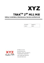
XYZ 

TRAK

TM

 2

OP

 M11 Mill


Safety, Installation, Maintenance, Service and Parts List 


Document: 

P/N 28170-1 

Version: 

050919 


Summary of Contents for TRAK 2OP M11 Mill

Page 1: ...ark Burlescombe Tiverton Devon EX16 7LL T 01823 674200 F 01823 674201 e mail sales xyzmachinetools com www xyzmachinetools com XYZ TRAKTM 2OP M11 Mill Safety Installation Maintenance Service and Parts...

Page 2: ...effort has been made to include all the information required for the purposes of this guide XYZ Machine Tools assumes no responsibility for inaccuracies or omission and accepts no liability for damag...

Page 3: ...s 43 5 1 The Machine Tool Setup 5 2 The Mechanical Drive Train 5 3 Computer Module 5 4 Programming Panel 5 5 Axis Motors Servos 5 6 Spindle Motor Inverter 5 7 Electrical 5 8 Tool Carrier Diagnostics 5...

Page 4: ...X Axis Drive Train 27520 1 Y Axis Drive Train 27564 2 Z Axis Drive Train 27540 1 Programming Panel Assembly 28160 ATC Assembly 27587 1 Spindle Head Assembly 27500 1 Spindle Cartridge Assembly 27830 1...

Page 5: ...luminium titanium or Materials which generate hazardous dusts when machined e g Tufnol beryllium This machine is designed to be used in a standard workshop environment only It must not be used in pote...

Page 6: ...oil or coolant Always use a chip scraper or brush o Before you make an adjustment to the part vice coolant nozzle or take measurements o Before you open guards Never reach around a guard to gain acce...

Page 7: ...one is in front behind or to the side of the machine when it is on the pallet truck whether stationary or being moved TO MOVE THE MACHINE PLEASE FOLLOW THE STEPS BELOW 1 Move the X axis to the approx...

Page 8: ...e personal injury and or damage to the equipment Warning labels on the machine are orange in color CAUTION Hazards or unsafe practices which could result in minor personal injury or equipment product...

Page 9: ...5 XYZ Machine Tools Ltd TRAK 2OP Installation Maintenance Service Part List Manual...

Page 10: ...6 XYZ Machine Tools Ltd TRAK 2OP Installation Maintenance Service Part List Manual...

Page 11: ...7 XYZ Machine Tools Ltd TRAK 2OP Installation Maintenance Service Part List Manual...

Page 12: ...8 XYZ Machine Tools Ltd TRAK 2OP Installation Maintenance Service Part List Manual...

Page 13: ...9 XYZ Machine Tools Ltd TRAK 2OP Installation Maintenance Service Part List Manual...

Page 14: ...hen allows you to push it back 1 7 Noise Levels The A weighted emission sound pressure level at the operator s workstation is less than 70dB A measured in accordance with EN ISO 11202 1995 and EN 1241...

Page 15: ...mum load 227kg Ball Lock hold down force 1020kg 4Nm torque Travel X axis 356mm Y axis 457mm 305mm of machining travel Z Axis 432mm Maximum distance from spindle nose to table surface 514mm Minimum dis...

Page 16: ...the machine Maximum demand 100 l min 18 SCFM Coolant Capacity 55 litres Machine Layout Dimensions in inches 2 2 Maximum Spindle Torque and Horsepower The following graphs illustrate the continuous an...

Page 17: ...coolant and machine adjustments 2 3 ProtoTRAK TMX Control Hardware 2 3 1 Programming Panel Assembly The programming panel assembly is mounted to the front right side of the machine The panel consists...

Page 18: ...vo drives motor signals and feedback and all the inputs and outputs The computer module assembly comprises a computer motherboard applications board and power supply 2 3 4 Servo Motors The TRAK 2OP mi...

Page 19: ...ydraulics that should be monitored on a regular basis If there is a leak in the system the oil in this reservoir will go down This leak will need to be fixed This oil cup is found on top of the machin...

Page 20: ...tch which is used to home the mill The machine must be homed each time the control is powered on Warning It is not recommended that the position of the home switches be changed They are preset at the...

Page 21: ...3 Status Light The machine has a green call light attached to the top of the machine to give the user information about the machine status a The light illuminates steady when the machine is running a...

Page 22: ...e Part List Manual DANGER You must turn off and lock out the power to the machine before adjusting any wiring at the transformer Failure to do so may cause death by electrocution Figure 2 4 17 Transfo...

Page 23: ...ve the pallet truck and any other loose items from the pallet Undo the 4 nuts securing the machine to the pallet Fig 3 1 arrow 1 Remove the bolt down brackets Fig 3 1 arrow 2 Fig 3 1 Insert the forkli...

Page 24: ...t the two side panels and rear panel with the screws supplied in a bag attached to the door handle see Fig 3 4 Fig 3 4 Move the machine into position Remove both side maintenance panels held in place...

Page 25: ...able Entry M32 compression cable gland Plug to suit your factory installation e g 32A Commando plug Connect an air line to the pneumatic input on the rear of the machine Switch on the machine Press th...

Page 26: ...axis movement time Each cycle of the lube pump lasts for 4 seconds Discharge frequency and length can be adjusted in service code 300 Discharge Pressure Approximately 140 psi To adjust the discharge...

Page 27: ...e following error messages will appear depending on which one is active If both are active the LUBE LEVEL LOW message is displayed 1 ERROR 5265 LUBE LEVEL LOW The lube pump level is low You will not b...

Page 28: ...e pump should also cycle 1 time when the SERVO ON button is pressed 10 Remove the head support bracket and parts used to hold the ATC in place WARNING Refer to section 3 2 before proceeding Install th...

Page 29: ...ETUP mode and press LOAD TOOLS Follow the message and press GO The ATC should come forward Remember the door must be shut Hit RETURN once it comes out and it should prompt you to press GO again to mov...

Page 30: ...sh down lines are adjusted properly See section 5 10 for a picture of how they should be adjusted One line should be directed toward the rear door and one toward the rear of the table to wash chips aw...

Page 31: ...3 9 X Y axis Drive Trains are loose Check Repeatability using the Repeatability and Positional Accuracy procedure Step by step carefully inspect the Drive Train for any looseness It may be necessary...

Page 32: ...ry Part Has the Same Error Possible Cause Check This Machine Tool Setup problem See Machine Tool Setup Section 5 1 Programming Error In the program look for common errors in programming such as transp...

Page 33: ...ck feedrate override Service code 503 set to a low value and now the machine is running that rapid speed Check the setting of service code 503 See service code diagnostics section 5 11 The control is...

Page 34: ...n Turn the EHW on the axis in question and see if the noise goes away Possible Cause Check This Too much backlash entered in Code 128 Recheck the machine s backlash Values should be less than 0 08mm I...

Page 35: ...h a no signal on the screen Possible Cause Check This VGA cable is not connected correctly Verify connection at computer module and at programming panel Computer module failure See computer module dia...

Page 36: ...the fault history stored in the servo amp See section 5 5 for more information on how to do this For a constant fault see below Possible Cause Check This Connection problem with Motor Encoder cable V...

Page 37: ...o the computer module Computer Module failed See Computer diagnostics Section 5 3 4 3 8 System Shuts Off During operation the system shuts off and will not turn back on Possible Cause Check This Fuse...

Page 38: ...axis will hit the hard stop and produce a servo error This is noticeable because the axis will move only toward the end stop it will not back up away from the stop Check each home switch input light...

Page 39: ...Do the following Service Codes and procedures Code 510 Spindle Setup set spindle orientation Possible Cause Check This The coupling that couples the motor to the spindle has come loose This is only li...

Page 40: ...d visually inspect for damage and replace as necessary 4 4 4 Air is not blowing through the spindle during a tool change Air should blow through the spindle when a tool holder is being removed whether...

Page 41: ...itial power up of the control and every 30 minutes of axes movement The control monitors the lube pump for oil level and pressure and will produce an error when either are a problem Do the following S...

Page 42: ...the procedure This will test for uni directional repeatability If the measurement does not repeat you have a repeatability problem that must be resolved Test for accumulative error by moving the axis...

Page 43: ...ure there is sufficient contact between the tool holder and the spindle See Machine Tool Setup Section 5 1 Part has been programmed wrong Check the programming of your part to make sure no errors were...

Page 44: ...ng proper lubrication If not check to make sure that the lube pump is functioning properly Also check for any pinched or blocked oil lines Machine Tool and Setup problem Check for any looseness in the...

Page 45: ...the motor should be replaced Spindle Drive may be in Local Mode and cannot be run from the Pendant On the Spindle Drive push the PU If the PU letters under the display are red then the drive is in lo...

Page 46: ...tuations then it is important to look at setup and tooling being used Ask the following questions Is the cutter dull Is the tool loose in the holder Am I taking a bigger cut than is possible on the ma...

Page 47: ...rity is checked Machine not level or after a heavy crash Water in air lines Faulty solenoid valves Rust Problems with the pneumatics on the tool carrier and tool change air cylinder User does not drai...

Page 48: ...e below Poor finish Machine chatter Excessive speeds and feeds can break cutting tools or wear tools prematurely Poor Tooling Using the wrong cutter for an application Entering the wrong size diameter...

Page 49: ...ecting the Axis from a Crash The machine has a few means to help prevent crashes The first line of defense is a soft limit that is built into the software The values are set from the factory and can b...

Page 50: ...The computer module contains a number of LED s that can be used for troubleshooting The following summarizes the LED s and how they work See figure 5 3b 1 Input LED s A small green LED is located nex...

Page 51: ...uld be off when negative input is on and vice versa YB Y axis ZB Z axis SPB Spindle HWB Handwheel WDT Watchdog Timer This light should be off when the computer is behaving normally and the software is...

Page 52: ...verlay Interface board If the Programming panel keys are not operating correctly this cable may be at fault 8 Machine ID port Machine ID key plugged in here to identify the machine type to the softwar...

Page 53: ...49 XYZ Machine Tools Ltd TRAK 2OP Installation Maintenance Service Part List Manual Figure 5 3b Computer module Side View...

Page 54: ...g rigid tapping 4 SPD_ORT signal is 24 DC Volt digital signal from the AC Drive that is used to command the spindle to go to the orientation angle for a tool change This is the MI3 terminal on the AC...

Page 55: ...Volt DC power signal used for triggering the critical overlay keys 4 ON KEY is a 24 Volt DC digital signal that is used to command the spindle motor to turn on 5 OFF KEY is a 24 Volt DC digital signa...

Page 56: ...wheel Digital Input Errors Make sure the LEDs to the corresponding digital input turn OFF and ON as expected Use service code 521 to test all the inputs to the computer module Digital Output Errors Ma...

Page 57: ...m Will not boot up or error on boot up Try disconnecting all cables one at a time until only the 115 Power Input VGA and Overlay Power cable are connected to the computer module if it still errors out...

Page 58: ...This button must be pressed upon boot up or after an e stop condition is resolved 3 VGA Cable Carries the video signal from the computer module to the LCD controller board 4 Com Port Cable Provides a...

Page 59: ...oard and the LCD screen 5 LCD Backlight Power Cable To power the backlight on the LCD 6 Overlay Interface Board Responsible for sending and receiving signals to and from the programming panel and comp...

Page 60: ...56 XYZ Machine Tools Ltd TRAK 2OP Installation Maintenance Service Part List Manual Figure 5 4b Programming Panel Rear View Figure 5 4c LCD User Interface Board...

Page 61: ...onnections to LCD controller board and inverter board See Fig 5 4b Electronic Handwheel does not work Unable to jog an axis Make certain that the jog speed key you want is pressed and you have selecte...

Page 62: ...all lock locations and code 520 to re set the ATC tool positions 5 5 2 Servo Drivers The servo drivers control the axes motors They run on a single phase 220 volt power supply derived from the power c...

Page 63: ...59 XYZ Machine Tools Ltd TRAK 2OP Installation Maintenance Service Part List Manual Figure 5 5 2b Servo Driver Parts...

Page 64: ...lts can be cleared by pressing the Servo on button except for faults 4 11 23 through 29 31 and 35 which require power to be cycled Display Alarm Name Alarm Description Servo Status AL001 Over current...

Page 65: ...o Off AL018 Abnormal signal output The encoder output exceeds the rated output frequency Servo Off AL019 Serial Communication Error RS 232 485 communication is in error Servo Off AL020 Serial Communic...

Page 66: ...vo drive exceeds the setting level AL083 will be triggered to protect IGBT Servo Off AL085 Regeneration error Regeneration control is in error Servo Off AL099 DSP Firmware Upgrade EEPROM has not been...

Page 67: ...mechanical problem drive train computer module servo drive axis motor or the following cables cable from computer module to servo drive encoder cable from servo to servo drive motor power cable from s...

Page 68: ...ossibility of death by electrocution The inverter stores energy after power is removed Allow 5 minutes for the energy to dissipate before servicing The charge light behind the front cover goes out onc...

Page 69: ...e all 24VDC and 2 output signals to the computer module Inputs and outputs are referred to terminal DCM Inputs 1 FWD FWD terminal input Commands the AC drive to rotate the spindle in the forward direc...

Page 70: ...r will turn red when in this mode 3 User Define Displays user defined information The factory default is the digital input status from the computer module Note the letter U on the top left of the oper...

Page 71: ...Verify that the wiring on the AC drive is correct 4 Verify that the parameters on the AC drive are correct The AC drive has a Fault which cannot be cleared Verify that the spindle Reset signal is bei...

Page 72: ...e computer module and to power the LCD controller board The voltage can be measured between pin 3 of the Overlay Power Port and the chassis ground on the computer module as seen on figure 5 7 1b 6 10V...

Page 73: ...Type Coolant and Lube pumps F1 5A Computer module 1 x Slow blow Computer module power supply F2 4A 3 phase Power supply F4 F5 and F 3x16A Electrical Cabinet 10x38mm Gg Spindle AC Drive F7 F8 and F9 3...

Page 74: ...o be set correctly using Service code 520 See section 6 13 for a procedure All 8 locations should be set by using a dial indicator to sweep in the taper on a tool The X and Y coordinate should be with...

Page 75: ...er one near each end Each sensor has an LED light which illuminates to indicate when the air cylinder has reached the fully retracted or extended position When the ATC is back the rear LED light shoul...

Page 76: ...chips accumulated between the ATC and the back of the table that air pressure is available and that the ATC limit switches are functioning properly When moving forward the ATC did not detected the fro...

Page 77: ...d the cause of the low air pressure Pressure should be 90 psi at the machines regulator clean or replace filter The solenoid is not receiving an electrical signal Check the LED light on the computer m...

Page 78: ...ogs of the spindle as an extra measure to prevent coolant from getting inside the spindle 5 9 5 Air Pressure Switch The 2 OP is equipped with an air pressure switch that monitors the air pressure supp...

Page 79: ...ting has been completed Warning Do not activate the valve 2 manually if the Y axis is not completely forward 0 40 inches past the actual soft limit or if the Z axis is not in its upper most position F...

Page 80: ...t of tools Operate the ATC forward and backwards Slowly wind out the adjustment screw until the deceleration of the ATC is smooth and soft Rear Flow Control mounted on the exhaust port of the quick ex...

Page 81: ...ontrolling the air going into the cylinder is used this flow control is commonly known as a metering in type labeled 4 on drawing 27563 2 Initial adjustment close the flow control all the way mark the...

Page 82: ...voir tank This valve must remain closed during normal operation 5 9 14 Air Quality Air quality is very important in the pneumatic system of the 2 OP Mill The most common problem with the compressed ai...

Page 83: ...ining fast enough and causes low coolant flow the screen needs to be cleaned The screens simply rests on top of the coolant tank 5 10 4 Coolant Hoses There are 2 coolant hoses attached to the coolant...

Page 84: ...ool Carrier Locations Use to set the 8 ATC tool locations as well as the tool change height 530 Set Machine Computer Module Serial Numbers Used to set the machines serial number motherboard MAC addres...

Page 85: ...r service representative asks to identify what version s of software is being run on your machine Code displays Software Version the version of the software you have installed Operating System Version...

Page 86: ...ulated your values enter them through Service Code 122 5 11 2 2 CODE 123 Calibration See Section 7 1 for a further explanation of this code 5 11 2 3 CODE 128 Input Backlash Constant Code 128 allows yo...

Page 87: ...e X and Y coordinate should be within 0 1mm on the indicator In other words there is some room for error but these tool locations cannot be set by eye The Z tool change height is defined as the locati...

Page 88: ...akes you to the bottom of the file and then changes to data top which will take you back to the top If you press MORE you can turn the log on and off the default is on The log should not be turned off...

Page 89: ...ffer is between 90 and 100 full When the top one is black and the rest are green the buffer is between 80 and 90 full The example at the right shows the buffer is between 70 and 80 full When it gets b...

Page 90: ...needs to be checked before any outputs can be triggered Warning Be careful when commanding the ATC to move in this service code as it may cause the ATC to slam into the back of the table The table may...

Page 91: ...d troubleshooting tools The NC ready and enable spindle test buttons must be pressed before you can proceed 5 11 4 Group D Operator Defaults Options Codes The following codes allow the user to set pro...

Page 92: ...al service codes that must be performed after working on certain aspects of the machine Service Code When Consequence 500 Setting ball lock locations for X and Y 1 Motor removed or replaced 2 Motor be...

Page 93: ...file 1 Replace computer module Machine will crash if 1 or more set ups are incorrect The following service code settings will be wrong 123 128 134 500 505 and 510 520 Setting the ATC locations 2 ATC...

Page 94: ...e ball locks Removal of the X Motor 1 Remove RH side enclosure sheet metal cover s to access the X axis motor Figure 6 1 1a Figure 6 1 1a 2 If the machine can be jogged under power go to Service Code...

Page 95: ...tor on the shelf portion of the X motor casting above the motor cavity Connect the encoder and power cables 12 Maneouvre the motor into the cavity taking care to not damage the cables Fasten the motor...

Page 96: ...1 If the machine can be jogged under power go to Service Code 505 and jog the Y axis forward use the finest resolution when you get near the limit switch until the POS Y AXIS LIMIT SWITCH flashing war...

Page 97: ...tall the belt Set the tension such that the belt can be twisted no more than 45 do not over tighten Torque the motor bracket M8 bolts to 24Nm 18ft lbs and re check belt tension 10 Reset the E stop and...

Page 98: ...e with half of the coupler attached to the motor s shaft Mark the position of the motor shaft key way on the coupler Remove the coupler Figure 6 1 3b 8 If the machine cannot be jogged under power it i...

Page 99: ...y loosen the second upper coupling bolt 8 Reset the E Stop and go back into Service code 505 9 Use the EHW to rotate the motor shaft inside of the coupling from its current positon by the amount the i...

Page 100: ...t called spindle port A new cable will come on the replacement AC drive so do not disconnect this from the drive you are removing 5 Undo the single screw press in the two tabs on the side of the cover...

Page 101: ...a USB device that contains all important machine parameters Refer to section 5 3 for a drawing of the computer module and cable connections 1 If you do not have a copy of your configuration file and t...

Page 102: ...nstallation Maintenance Service Part List Manual Figure 6 5a 4 Using a 6mm hex key to prevent the ballscrew from rotating remove the hex nut star washer flat washer pulley ferrule and the clamp nut Se...

Page 103: ...own in figure 6 5d Figure 6 5d 6 Remove the five SHCS that secure the ballnut to the X axis yoke 7 Remove the four SHCS that secure the bearing cap found opposite to where the cushion seats also shown...

Page 104: ...e head to near the full length of travel to the right but not against the cushion This will align the ballnut to the angular contact bearings 10 Tighten the four SHCS that secure the bearing housing t...

Page 105: ...and belt 3 Remove the Y axis motor plate bracket 4 Remove the hex nut star washer pulley ferrule key and clamp nut from the back end of the ballscrew 5 Remove the four SHCS that secure the ATC magazi...

Page 106: ...er the Y Axis casting back into place 11 Align the Y Axis casting and install roll pins 12 Secure the Y Axis casting to the bed of the machine 13 Drive the saddle to near the full length of travel to...

Page 107: ...the inside of the machine Ensure unauthorised personnel are kept away from the machine when you are working inside Please refer to assembly drawing 27540 1 found at the back of this manual 1 Remove th...

Page 108: ...S that fasten the bearing housing to the top of the column 17 Remove the ballscrew by sliding it upward and towards the bridge allowing the ballnut to clear Disassembling the Z axis Ballscrew 1 Remove...

Page 109: ...listen for the air to stop escaping from around the tool holder then back up one click Enter the Z tool change offset that is displayed in the lower right hand gray box 6 8 Spindle Motor Replacement W...

Page 110: ...the removal and replacement procedure it is often necessary to jog the axes to gain access to various parts of the machine To minimise the risk of serious injury through crushing you must power down o...

Page 111: ...evant switch but ensuring there is still a small amount of plunger travel left to avoid damaging the switch 10 Enter service code 510 to set spindle orientation and follow the on screen instructions 6...

Page 112: ...lts that hold the ATC in place It is also keyed forwards backwards only to aid re fitting in the correct place 5 Remove the ATC casting from the machine and replace with the new one 6 Align the ATC si...

Page 113: ...o this system the tool unclamping process will not work correctly This is usually indicated by seeing oil leaks at connections or seeing air bubbles in the oil reservoir see figure 6 15 Figure 6 15 Pl...

Page 114: ...r of the machine For the Z axis it may be easiest to move the head down toward the table 2 Turn power off to the machine 3 See drawing 27658 1 for an illustration of where each home switch is mounted...

Page 115: ...ng opening 4 Remove the four screws around the base of the Spindle Fan shroud and remove the shroud 5 Remove the 3 screws that secure the spindle fan in place and remove the fan 6 Loosen the 2 grub sc...

Page 116: ...the X and Y tool position locations and tool change height The home switches that come on the 2 OP should not normally need to be adjusted unless a component that is part of the drive train is changed...

Page 117: ...6 Hook the new servo over the lower mounting screw and then install the other mounting screws Tighten all screws 7 Connect all wires to the appropriate terminals 8 On the Z axis servo remove the link...

Page 118: ...drive and enter this value under parameter 10 19 a Press the Program Data button on the drive b Use the up and down arrows to scroll to 10 and press Program Data c Now use the up and down arrows to sc...

Page 119: ...Set a 2 m indicator in the spindle and move it up to one side of the gauge block or standard 2 Go to setup mode and enter Service Code 123 3 Select the axis you want to calibrate X Y or Z 4 Follow the...

Page 120: ...check the coolant level add if needed 5 Visually check the air supply filter Monthly 1 Remove back ATC and Y axis motor compartment access covers and clean chips and any other debris Cleanup any oil o...

Page 121: ...TION SOUTHWESTERN INDUSTRIES INC 2615 HOMESTEAD PLACE RANCHO DOMINGUEZ CA 90220 5610 1 10 31 14 RS PROTOTYPE RELEASE A 14255 1 14 15 TO PRODUCTION RELEASE A DETAIL A 17 12 49 55 61 8 48 4X 65 4X 9 48...

Page 122: ...7689 1 BELLOW LEFT 300mm H 1 EA R PS KING RICH OP443011 10 27689 2 BELLOW RIGHT 300mm H 1 EA R PS KING RICH OP443021 11 27689 3 BELLOW LEFT 70mm H 1 EA R PS KING RICH OP443010 12 27689 4 BELLOW RIGHT...

Page 123: ...AXIS DC300 133_3 2M 1 EA C R PL 33 26844 5 CABLE ASSY MOTOR ENCODER DELTA Y AXIS 1 EA B R PL 34 27682 COVER ASSY TOOL 2OP 1 EA A R PL 35 28087 PIN PIVOT ATC DOOR ASSIST CYLINDER 1 EA R DWG 36 24768 1...

Page 124: ...R FINISH WASHER FINISH 35 OD x 17 ID x 6mm H NON STOCKABLE 6 EA R PS 64 M6 70B WASHER FLAT USS STL BO 13 EA R PS 65 M5 73B WASHER SPLIT LOCK STL BO 39 EA R PS 66 M5 70B WASHER FLAT USS STL BO 5 EA R P...

Page 125: ...RES MILL INDEXER INPUTS UNCLAMP BT ATC BACK TOOL UNCLAMP DOOR Y HOME SERVO ON BT ATC FRONT TOOL CLAMP Z HOME X HOME AIR PRESSURE E STOP SPARE 4 SPARE 3 MILL INDEXER SPARE 3B START KEY LED SPARE LED ST...

Page 126: ...CODER CABLE WIRE CHART MOTOR FAN 0V 115AC 2 MOTOR FAN MOTOR POWER F4 F5 F6 F7 F8 F9 F4 F5 F6 F7 F8 F9 TB1 TB2 TB3 TB4 TB5 TB6 TB7 TB8 TB9 TB10 TB11 TB12 TB13 TB1 TB2 TB3 TB4 TB5 TB6 TB7 TB8 TB9 TB10 T...

Page 127: ...80 4 CABLE ASSY PN 27635 7 CABLE ASSY PN 27635 8 TOOL CLAMP PN 22680 4 CABLE ASSY PN 27635 5 COM NO NC COM NO NC NO DOOR LOCK SPARE 2A OUTPUTS Z AXIS BRAKE ATC BACK SPARE 1 SPARE 3A TOOL UNCLAMP ATC F...

Page 128: ...PN 26938 5 ATC BACK ATC FRONT A B S P R CABLE ASSY PN 27635 15 F4 F5 F6 F7 F8 F9 TB1 TB2 TB3 TB4 TB5 TB6 TB7 TB8 TB9 TB10 TB11 TB12 TB13 DOOR LOCK SPARE 2A OUTPUTS Z AXIS BRAKE ATC BACK SPARE 1 SPARE...

Page 129: ...GES MASK ALL TAPPED HOLES DIMENSIONING PER ASME Y14 5 6 5 14 RO 6 5 14 Sal THIRD ANGLE PROJECTION SOUTHWESTERN INDUSTRIES INC 2615 HOMESTEAD PLACE RANCHO DOMINGUEZ CA 90220 5610 3 9 3 14 RO REVISED FL...

Page 130: ...1 14 15 1 8 15 12 15 14...

Page 131: ...1 EA R PS KING RICH OP420841 9 27603 9 SUPPORT LEFT RIGHT UPPER STRUCTURE SEE 27520 2 EA R PS KING RICH OP420500 10 27603 10 COVER CONDUIT MINOR UPPER STRUCTURE SEE 27520 1 EA R PS KING RICH OP420420...

Page 132: ...1 EA R PS KING RICH OP420990 43 24404 3 LEXAN WINDOW DOOR 2OP 2 EA R PS KING RICH A 82 019 44 27560 FRAME LEXAN WINDOW 2 EA R PS KING RICH OP420120 45 27897 WELDMENT DOOR SHAFT AND LEVER ARM 1 EA A R...

Page 133: ...ASSY SERVO ON BUTTON DC300 124 1 EA A R PL 71 23262 2 CABLE TIE HOLDER 0 75 x 0 75 x 0 188 1 EA A R DWG 72 22475 TIE WRAP 4 IN PLASTIC 1 EA R DWG 80 M5 0 8X10 27Z SCREW BHCS STL ZINC NON STOCKABLE 26...

Page 134: ...PS 100 M5 73B WASHER SPLIT LOCK STL BO 10 EA R PS 106 M10 71B WASHER FLAT SAE STL BO AR EA R PS 110 M22 73Z WASHER SPLIT LOCK STL ZINC NON STOCKABLE 2 EA R PS 112 M10 56Z NUT NYLON LOCK STL ZINC NON...

Page 135: ...11 EURO 27542 2 9 11 14 Bob B DIMENSIONS ARE IN INCHES DEC X 1 XX 01 XXX 005 ANGLES XX 0 30 FRACTIONS 1 8 FINISH 125 RMS REMOVE ALL SHARP EDGES MASK ALL TAPPED HOLES DIMENSIONING PER ASME Y14 5 1 8 15...

Page 136: ...PLACE RANCHO DOMINGUEZ CA 90220 5610 A DETAIL A 23 4X 24 4X 75 12X 85 4X 7 70 5X 82 5X 1 REF 8 70 5X 82 5X 9 70 4X 82 4X 10 70 6X 82 6X 11 70 4X 12 70 5X 82 5X 32 REF 71 2X 84 2X 17 74 80 2X 2X 16 73...

Page 137: ...Y SEE 27542 1 EA R PS KING RICH OP420290 11 27530 9 COVER FRONT LEFT FRAME ASSY SEE 27542 1 EA R PS KING RICH OP420260 12 27530 10 COVER REAR LEFT LUBE PUMP SEE 27542 1 EA R PS KING RICH OP420240 13 2...

Page 138: ...IFOLD TUBE FITTING 4 OUTLETS SEE 27591 1 EA R PS KING RICH 34 27725 CHECK VALVE STRAIGHT 1 4 BSPT SEE 27563 1 EA R PS KING RICH 35 27745 COUPLING 1 4 BSPT SEE 27563 1 EA R PS KING RICH 36 27085 2 FITT...

Page 139: ...7 4 WIRE HARNESS ASSY 3 CONN TRX TO DRIVE EURO 1 EA A R PL 57 28112 1 TRAY TRANSFORMER 2OP M11 1 EA A R PS KING RICH OP420251 B 58 28111 BEARING DRAWN CUP NEEDLE ROLLER HK1308 4 EA A R PS KING RICH A...

Page 140: ...ZINC NON STOCKABLE 65 EA R PS 83 M5 73B WASHER SPLIT LOCK STL BO 2 EA R PS 84 M6 73B WASHER SPLIT LOCK STL BO 24 EA R PS 85 M8 73B WASHER SPLIT LOCK STL BO 4 EA R PS 86 M6 70B WASHER FLAT USS STL BO...

Page 141: ...125 RMS REMOVE ALL SHARP EDGES MASK ALL TAPPED HOLES DIMENSIONING PER ASME Y14 5 7 9 14 TO 7 8 14 Sal REV ECN DATE APPRV DESCRIPTION REVISIONS A B C D A B C D 1 2 3 4 5 6 7 8 1 2 3 4 5 6 7 8 THIRD AN...

Page 142: ...RIAL FINISH DRIVE TRAIN ASSY X AXIS M11 27520 1 1 10 13 Bob B DIMENSIONS ARE IN INCHES DEC X 1 XX 01 XXX 005 ANGLES XX 0 30 FRACTIONS 1 8 FINISH 125 RMS REMOVE ALL SHARP EDGES MASK ALL TAPPED HOLES DI...

Page 143: ...ENGINEER CHECKER FE MATERIAL FINISH DRIVE TRAIN ASSY X AXIS M11 27520 1 1 10 13 Bob B DIMENSIONS ARE IN INCHES DEC X 1 XX 01 XXX 005 ANGLES XX 0 30 FRACTIONS 1 8 FINISH 125 RMS REMOVE ALL SHARP EDGES...

Page 144: ...G 12 27951 4 LOCKNUT M20 X 1 0 1 EA R PS KING RICH 13 27603 9 SUPPORT LEFT RIGHT UPPER STRUCTURE SEE 27520 2 EA R PS KING RICH 14 27603 10 COVER CONDUIT MINOR UPPER STRUCTURE SEE 27520 1 EA R PS KING...

Page 145: ...0 1 EA R PS 33 27603 21 BRACE RIGHT X AXIS ASSY SEE 27520 1 EA R PS 34 27634 TRIGGER HOME SWITCH 2 OP 1 EA R PS KING RICH OP360011 35 28042 2 MANIFOLD TUBE FITTING 6 OUTLETS 1 EA R PS KING RICH 36 226...

Page 146: ...EXT TOOTH STL ZINC 1 EA R PS 58 1 2 66Z WASHER FLAT NARROW ANSI TYPE B 1 EA R PS 59 M4 70Z WASHER FLAT STL ZINC 33 EA R PS 60 1 4 73B WASHER SPLIT LOCK STL BO 4 EA R PS 61 M4 70B WASHER FLAT STL BO 2...

Page 147: ...TAPPED HOLES DIMENSIONING PER ASME Y14 5 TO Sal A B C D A B C D 1 2 3 4 5 6 7 8 1 2 3 4 5 6 7 8 THIRD ANGLE PROJECTION SOUTHWESTERN INDUSTRIES INC 2615 HOMESTEAD PLACE RANCHO DOMINGUEZ CA 90220 5610 2...

Page 148: ...CON SENT OF SOUTHWESTERN INDUSTRIES DATE APPROVALS DRAWN BY ENGINEER CHECKER FE MATERIAL FINISH DRIVE TRAIN ASSY Y AXIS M11 EURO 27564 2 9 9 14 Bob A DIMENSIONS ARE IN INCHES DEC X 1 XX 01 XXX 005 ANG...

Page 149: ...9 16350 FERRULE SPROCKET DRIVE 1 EA R DWG 10 27513 SPROCKET 26 TEETH W O GUIDES 1 EA A R DWG 11 27526 BUMPER Y AXIS FIXED END 1 EA R DWG 12 27951 4 LOCKNUT M20 X 1 0 1 EA R PS KING RICH 13 27527 BUMP...

Page 150: ...HT SEE 27564 1 EA R PS 42 27998 4 WIPER REAR LEFT RIGHT 2 EA A R DWG 43 27679 2 COVER WIPER REAR WORKTABLE SEE 27564 1 EA R PS 44 27634 TRIGGER HOME SWITCH 2 OP 1 EA R PS KING RICH OP360011 45 27691 1...

Page 151: ...PS 67 M6 1 0X20 27B SCREW BHCS STL BO 24 EA R PS 68 M6 1 0X12 25B SCREW SHCS STL BO 2 EA R PS 69 M8 1 25X25 25B SCREW SHCS STL BO 4 EA R PS 70 M5 0 8X15 25B SCREW SHCS STL BO NON STOCKABLE 2 EA R PS...

Page 152: ...s Rev Stat Type Mfr Mfr P N 27564 2 Printed 11 24 2014 Rev A DRIVE TRAIN ASSY Y AXIS M11 EURO 93 M6 70B WASHER FLAT USS STL BO 4 EA R PS SOUTHWESTERN INDUSTRIES INC 2615 HOMESTEAD PLACE RANCHO DOMINGU...

Page 153: ...TAIL B 26 35 77 6X 86 6X 76 4X 84 4X 66 4X 83 4X C DETAIL C 50 52 51 50 4X 51 47 46 49 2X 48 92 4X 45 33 35 REF 75 4X 86 4X D DETAIL D 70 2X 34 58 41 42 43 2X REF 24 2X 25 2X 79 6X REAR VIEW OF COLUMN...

Page 154: ...1 27540 1 6 9 14 Bob C 8 7 14 TO 7 31 14 Sal A B C D A B C D 1 2 3 4 5 6 7 8 1 2 3 4 5 6 7 8 THIRD ANGLE PROJECTION SOUTHWESTERN INDUSTRIES INC 2615 HOMESTEAD PLACE RANCHO DOMINGUEZ CA 90220 5610 1 4...

Page 155: ...al A B C D A B C D 1 2 3 4 5 6 7 8 1 2 3 4 5 6 7 8 THIRD ANGLE PROJECTION SOUTHWESTERN INDUSTRIES INC 2615 HOMESTEAD PLACE RANCHO DOMINGUEZ CA 90220 5610 3 3 37 REF 38 37 72 4X 39 40 72 4X 56 57 59 37...

Page 156: ...1 EA R PL 13 27756 NUT CLAMP Z AXIS 1 EA C R DWG 14 27085 2 FITTING AIR 90 10mm PUSH TO CONN 1 4 BSPT M SEE 27542 OR 27563 3 EA R PS KING RICH A 316 381 15 28071 2 VALVE FLOW CONTROL AIR 1 4 BSPT TO 6...

Page 157: ...EL FLANGE REAR PIVOT SEE 27540 OR 27540 1 1 EA R PS AIR TAC CA 174404 SNCL 32 L 40 27583 4 SWIVEL FLANGE MTG BRKT SEE 27540 OR 27540 1 1 EA R PS AIR TAC CB 174390 SNCB 32 SF 0 41 26840 6 CABLE ASSY MO...

Page 158: ...A R PS 62 28076 NIPPLE ROUND 1 8 BSPT X 2 LG SEE 27540 OR 27540 1 1 EA R PS 65 M6 1 0X20 25B SCREW SHCS STL BO 34 EA R PS 66 M8 1 25X35 25B SCREW SHCS STL BO 10 EA R PS 67 M8 1 25X40 25B SCREW SHCS ST...

Page 159: ...4 EA R PS 86 M5 73B WASHER SPLIT LOCK STL BO 12 EA R PS 87 M4 73B WASHER SPLIT LOCK STL BO 7 EA R PS 88 M5 70B WASHER FLAT USS STL BO 2 EA R PS 89 M4 70B WASHER FLAT STL BO 4 EA R PS 92 M8 70B WASHER...

Page 160: ...HOLES DIMENSIONING PER ASME Y14 5 1 10 14 TO 1 10 14 Sal REV ECN DATE APPRV DESCRIPTION REVISIONS 1 1 10 14 TO PROTOTYPE RELEASE A B C D A B C D 1 2 3 4 5 6 7 8 1 2 3 4 5 6 7 8 THIRD ANGLE PROJECTION...

Page 161: ...CTRONIC 1 EA A R PS 6 26040 CONTACT BLOCK E STOP 1 EA R PS TELEMECANIQUE ZB6E2B 8 27669 3 GASKET BEZEL 2 EA R DWG 9 27669 4 GASKET BEZEL 2 EA R DWG 10 26716 2 SWITCH ASSY PUSHBUTTON SERVO ON DBL POLE...

Page 162: ...S DRAWN BY ENGINEER CHECKER FE MATERIAL FINISH ATC ASSY 2 OP M11 MILL 27587 1 1 1 8 18 14 Bob A DIMENSIONS ARE IN INCHES DEC X 1 XX 01 XXX 005 ANGLES XX 0 30 FRACTIONS 1 8 FINISH 125 RMS REMOVE ALL SH...

Page 163: ...FT 1 EA R PS KING RICH OP520100 3 27575 1 BRACKET DOOR ASSIST RIGHT 1 EA R PS KING RICH OP520110 4 27615 WEAR STRIP DOOR ASSIST 2 EA R PS KING RICH OP520210 5 27493 GRIPPER ASSY TOOL CHANGER 4 EA R PL...

Page 164: ...K ALL TAPPED HOLES DIMENSIONING PER ASME Y14 5 TO Sal REV ECN DATE APPRV DESCRIPTION REVISIONS A 14218 10 24 14 TO PRODUCTION RELEASE A B C D A B C D 1 2 3 4 5 6 7 8 1 2 3 4 5 6 7 8 THIRD ANGLE PROJEC...

Page 165: ...OR 27500 1 2 EA R PS KING RICH 9 27507 PLATE MOUNTING LIM SW 1 EA R DWG 10 22680 4 SWITCH LIMIT PLUNGER SEE 27500 OR 27500 1 2 EA R PS 11 22874 1 PUSH BUTTON RESET N O CONTACT TOOL UNCLAMP 1 EA B R D...

Page 166: ...27495 2 SHEET METAL FRONT PANEL SPINDLE ASSY SEE 27500 OR 27500 1 1 EA R PS 37 27495 3 SHEET METAL LEFT COVER SPINDLE ASSY SEE 27500 OR 27500 1 1 EA R PS 38 27495 4 SHEET METAL LEFT PANEL SPINDLE ASS...

Page 167: ...ASHER FLAT DIN 125 BO NON STOCKABLE 10 EA R PS 77 M10 WASHER WASHER FINISH BRASS NON STOCKABLE 4 EA R PS 78 M5 73B WASHER SPLIT LOCK STL BO 42 EA R PS 79 M4 78Z WASHER FLAT DIN 125 ZINC NON STOCKABLE...

Page 168: ...S 1 8 FINISH 125 RMS REMOVE ALL SHARP EDGES MASK ALL TAPPED HOLES DIMENSIONING PER ASME Y14 5 12 1 14 TO 11 21 14 Sal REV ECN DATE APPRV DESCRIPTION REVISIONS B 14333 12 4 14 TO DELETED ITEMS 24 25 47...

Page 169: ...NG 1 SET 1 EA A R PL 9 27836 SPACER TOP BEARING SPINDLE 1 EA R DWG 10 27837 NUT SPANNER M50 1 EA R DWG 11 27839 NUT SPANNER M12 1 EA R DWG 12 27848 HOUSING TOP SPINDLE 1 EA R DWG 13 27841 COLLAR INNER...

Page 170: ...SHCS STL BO 8 EA R PS 43 M5 0 8X10 25B SCREW SHCS STL BO 2 EA R PS 44 M5 0 8X25 25B SCREW SHCS STL BO 2 EA A R PS 45 M5 0 8X30 25B SCREW SHCS STL BO NON STOCKABLE 6 EA R PS 46 M5 0 8X20 25B SCREW SHCS...

Page 171: ...X 43 2X 1 1 34 35 24 25 25 10 30 26 28 27 29 MAIN AIR PREPARATION UNIT AND ATC SOLENOID VALVE REV ECN DATE APPRV DESCRIPTION REVISIONS 10 31 14 TO PROTOTYPE RELEASE 26 51 2 2 AIR TANK 44 FOR PARTS LIS...

Page 172: ...1 1 1 1 2 1 30 2X SPINDLE ATC CYLINDER ATC DOOR ASSIST CYLINDER DOOR OPEN ASSIST CYLINDER TOOL CHANGE SOLENOID VALVE AND AIR OVER OIL CYLINDER WITH FITTINGS 13 23 20 41 9 42 2X 43 2X 1 1 34 35 46 45 2...

Page 173: ...TC Door Assist Cylinder QUICK EXHAUST VALVE FLOW CONTROL METER OUT WITH MUFFLER FLOW CONTROL METER OUT FLOW CONTROL METER IN IN OUT EXH DOOR CLOSE FLOW CONTROL METER IN DOOR CLOSE FLOW CONTROL METER O...

Page 174: ...583 5 CYLINDER AIR 20mm BORE X 60mm S 1 EA R DWG 10 27583 6 CYLINDER AIR 40mm BORE 125mm STROKE 1 EA R DWG 11 27502 3 CYLINDER ASSY TOOL UNCLAMP 1 EA A R PL 12 27502 2 RESERVOIR OIL MAKEUP TOOL UNCLAM...

Page 175: ...USH TO CONNECT 1 4 BSPT MALE THD 2 EA R PS KING RICH 34 27085 2 FITTING AIR 90 10mm PUSH TO CONN 1 4 BSPT M SEE 27542 OR 27563 3 EA R PS KING RICH A 316 381 35 28071 2 VALVE FLOW CONTROL AIR 1 4 BSPT...

Page 176: ...EVE COMPRESSION OUTER 6mm MANIFO LD 1 EA A R PS KING RICH 59 28047 3 SLEEVE COMPRESSION INNER 6mm MANIFO LD 1 EA A R PS KING RICH 60 22647 6 NIPPLE 1 4 BSPT x 3 0 LG 1 EA R PS KING RICH 61 22169 2 FIT...

Page 177: ...LICATION NEXT ASSY USED ON COOLANT SYSTEM ASSY 2OP MILL 27557 1 1 05 01 09 Sal A DIMENSIONS ARE IN INCHES DEC X 1 XX 01 XXX 005 ANGLES XX 0 30 FRACTIONS 1 8 FINISH 125 RMS REMOVE ALL SHARP EDGES MASK...

Page 178: ...L SEE 27557 1 EA R PS KING RICH 5 27176 1 CABLE ASSY COOLANT PUMP DC300 121 1 EA R PL 6 27615 1 WEAR PLATE CHIP TRAY 2OP 2 EA R DWG 7 28042 PLUG BSTP 3 4 14TPI SEE 27557 1 EA R PS KING RICH 8 28133 FI...

Page 179: ...A DIMENSIONS ARE IN INCHES DEC X 1 XX 01 XXX 005 ANGLES XX 0 30 FRACTIONS 1 8 FINISH 125 RMS REMOVE ALL SHARP EDGES MASK ALL TAPPED HOLES DIMENSIONING PER ASME Y14 5 TO Sal REV ECN DATE APPRV DESCRIP...

Page 180: ...SED ON LUBRICATION SYSTEM 2 OP M11 MILL 27591 1 7 8 25 14 Bob A DIMENSIONS ARE IN INCHES DEC X 1 XX 01 XXX 005 ANGLES XX 0 30 FRACTIONS 1 8 FINISH 125 RMS REMOVE ALL SHARP EDGES MASK ALL TAPPED HOLES...

Page 181: ...E ALL SHARP EDGES MASK ALL TAPPED HOLES DIMENSIONING PER ASME Y14 5 TO Sal REV ECN DATE APPRV DESCRIPTION REVISIONS A 14218 10 24 14 TO PRODUCTION RELEASE A B C D A B C D 1 2 3 4 5 6 7 8 1 2 3 4 5 6 7...

Page 182: ...USED ON LUBRICATION SYSTEM 2 OP M11 MILL 27591 1 7 8 25 14 Bob A DIMENSIONS ARE IN INCHES DEC X 1 XX 01 XXX 005 ANGLES XX 0 30 FRACTIONS 1 8 FINISH 125 RMS REMOVE ALL SHARP EDGES MASK ALL TAPPED HOLE...

Page 183: ...X 1 XX 01 XXX 005 ANGLES XX 0 30 FRACTIONS 1 8 FINISH 125 RMS REMOVE ALL SHARP EDGES MASK ALL TAPPED HOLES DIMENSIONING PER ASME Y14 5 TO Sal REV ECN DATE APPRV DESCRIPTION REVISIONS A 14218 10 24 14...
Page 184: ...R CHECKER FE MATERIAL FINISH APPLICATION NEXT ASSY USED ON LUBRICATION SYSTEM 2 OP M11 MILL 27591 1 7 8 25 14 Bob A DIMENSIONS ARE IN INCHES DEC X 1 XX 01 XXX 005 ANGLES XX 0 30 FRACTIONS 1 8 FINISH 1...

Page 185: ...XX 01 XXX 005 ANGLES XX 0 30 FRACTIONS 1 8 FINISH 125 RMS REMOVE ALL SHARP EDGES MASK ALL TAPPED HOLES DIMENSIONING PER ASME Y14 5 TO Sal REV ECN DATE APPRV DESCRIPTION REVISIONS A 14218 10 24 14 TO P...

Page 186: ...R PL 5 26979 2 TUBING PLASTIC SOFT 2mm ID x 4mm OD 767 IN R PS KING RICH 7 26972 2 VALVE CHECK METER SIZE 2 12 EA R PS KING RICH 8 26972 3 VALVE CHECK METER SIZE 5 3 EA R PS KING RICH 9 28048 ELBOW C...

Page 187: ...1 XX 01 XXX 005 ANGLES XX 0 30 FRACTIONS 1 8 FINISH 125 RMS REMOVE ALL SHARP EDGES MASK ALL TAPPED HOLES DIMENSIONING PER ASME Y14 5 9 10 14 TO 8 20 14 Sal REV ECN DATE APPRV DESCRIPTION REVISIONS A...

Page 188: ...3 27635 2 CABLE ASSY Y AXIS HOME SW DC300 112 1 EA R PL 4 27635 3 CABLE ASSY Z AXIS HOME SW DC300 113 1 EA R PL 5 27690 1 COVER HOME SWITCH X AXIS SEE 27520 1 EA R PS 6 27690 2 COVER HOME SWITCH Y AX...

Page 189: ...15 TB16 TB17 TB18 K2 K3 111 10X 115 10X 48 49 110 3X 35 36 37 112 4X 125 4X 54 1 15 3X 15 3X 18 3X 10 15X 25 5X 30 9 3X 23 7 33 26 4X 110 3X 53 ROUTE TRANSFORMER WIRE HARNESS ASSY A TB4 TB5 TB6 TB7 TB...

Page 190: ...CC1 BLUE NCR2 WHT NCR1 WHT TWH5 NCR1 BLK NCR2 BLK TWH4 TWH6 CC1 BRWN TB14 TB15 3 3 4 4 TWH8 DETAIL C ENCLOSURE ASSY SERVO DRIVES P N 28156 39 61 62 REF 60 REF 2 WIRE CABLE ITEM NUMBER WIRE FROM WIRE L...

Page 191: ...1 BLK BLACK WHITE FAN 2 L FAN 2 N GND WORK LIGHT CABLE EXTENSION ENCLOSURE ASSY SERVO DRIVES P N 28156 ENCLOSURE ASSY P N 27568 2 2 64 REF 63 REF 38 65 REF SPINDLE MOTOR P N 26849 4 WIRE ITEM NUMBER W...

Page 192: ...69 WIRE CABLE ITEM NUMBER WIRE FROM WIRE LABEL WIRE GAGE COLOR WIRE TO S11 0 33mm 2 BLACK K3 S11 S12 0 33mm 2 RED K3 S12 S21 0 33mm 2 WHITE K3 S21 S22 0 33mm 2 GREEN K3 S22 S33 0 33mm 2 WHITE K3 S33...

Page 193: ...DWG 12 26567 2 RELAY 24AC COIL 4PDT 1 EA A R DWG 13 23434 3 SOCKET RELAY RAIL MOUNT 1 EA R DWG 14 22891 2 RELAY DUAL CHANNEL 1 EA R DWG 15 23036 1 FUSE HOLDER 32 AMP 690V 6 EA B R DWG 16 23152 8 FUSE...

Page 194: ...K3 1 EA A R DWG 54 27621 5 LB2 LABEL TEXT ELEC ENCLOSURE 27621 5 1 EA A R DWG 55 27669 1 GASKET BEZEL ROLL 2104 MM R DWG 56 28157 SHEET METAL CABLE ENTRY OUTSIDE 2 EA B R DWG 57 28157 1 SHEET METAL C...

Page 195: ...GREEN YELLOW RING TO RING 120mm 1 EA R DWG 77 26555 992121 0300 WIRE ASSY 3 5mm GREEN YELLOW RING TO RING 300mm 1 EA R DWG 79 26555 381313 0900 WIRE ASSY 2mm WHITE FERRULE TO FERRULE 900mm 1 EA R DWG...

Page 196: ...L ZINC NON STOCKABLE 2 EA R PS 114 M6 1 0X12 25B SCREW SHCS STL BO 6 EA R PS 115 24009 4 WASHER BELLEVILLE SPRING LOCK 10 OR M5 SERRATED 13 EA R PS 116 M4 78Z WASHER FLAT DIN 125 ZINC NON STOCKABLE 4...

Page 197: ...O 5 13 2014 5 13 2014 REV DESCRIPTION DATE APVD REVISION ECN REV DESCRIPTION DATE APVD REVISION ECN REV DESCRIPTION DATE APVD REVISION ECN E STOP INPUT DOOR INPUT X HOME INPUT Y HOME INPUT Z HOME INP...

Page 198: ...Z CA 90220 5610 2 ENCLOSURE ASSY SERVO DRIVES 2OP M11 MILL EURO 28156 1 DIMENSIONS ARE IN MILLIMETERS 1 4 0 020 4 16 0 025 16 63 0 050 63 250 0 070 250 1000 0 100 1000 1500 0 200 REMOVE ALL SHARP EDGE...

Page 199: ...S TO BE CONNECTED TO TERMINALS P AND C 2A4 4 APPLY A SLEEVE LABEL ITEMS 70 74 TO BOTH ENDS OF EACH WIRE PER WIRE CHART 2C2 5 PLACE JUMPERS ITEM 28 AS SHOWN ON DRAWING 1B6 2C8 3 2 2 2 CABLE ITEM NUMBER...

Page 200: ...PPER RESISTOR 2OP M11 1 EA A R DWG KING RICH 8 27603 29 BRACKET MOUNTING SERVO ENCLOSURE 2OP M11 1 EA A R DWG KING RICH 12 26687 3 FOAM CABLE WAY 1 EA A R PS 13 28108 1 TAPE ADHESIVE FOAM 36YD ROLL DO...

Page 201: ...00 WIRE ASSY 2mm BLACK FERRULE TO FERRULE 400mm 2 EA R DWG 54 26555 081313 0150 WIRE ASSY 2mm BLACK FERRULE TO FERRULE 150mm 1 EA R DWG 55 26555 081313 0110 WIRE ASSY 2mm BLACK FERRULE TO FERRULE 110m...

Page 202: ...S STL BO NON STOCKABLE 7 EA R PS 87 M5 0 8X16 27B SCREW BHCS STL BO NON STOCKABLE 4 EA R PS 88 M5 0 8X14 25B SCREW SHCS STL BO NON STOCKABLE 3 EA R PS 90 M6 70B WASHER FLAT USS STL BO 8 EA R PS 91 M5...

Page 203: ...cover incidental costs such as installation labour etc XYZ is not responsible for consequential damages from use or misuse of any of its products ProtoTRAK products are precision mechanical electromec...

Reviews: