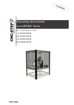
CNC-Step AceroDURO 100/S100, Operating Instructions Manual
The CNC-Step AceroDURO 100/S100 is a cutting-edge CNC machine designed to handle various materials with precision and ease. Unlock its full potential by accessing the comprehensive Operating Instructions Manual. Download this manual for free from our website to ensure optimal usage and unleash your creativity.
Share
Download


Reviews:
No comments
Related manuals for AceroDURO 100/S100
LO 65 Ec
Brand: Mafell Pages: 162
MR 40PB
Brand: Far Tools Pages: 24
TRAK 2OP M11 Mill
Brand: XYZ Machine Tools Pages: 203
YT-82380
Brand: YATO Pages: 96
RO 1600 PLU
Brand: F.F. Group Pages: 56
Genmitsu CNC
Brand: SainSmart Pages: 12
3663602796282
Brand: Erbauer Pages: 36
RE180PL1
Brand: Ryobi Pages: 44
52G710
Brand: VERTO Pages: 48
154699.01
Brand: ENKHO Pages: 48
MASLOW CNC
Brand: MAKER MADE Pages: 40
20731
Brand: Yeti Pages: 29
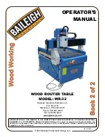
1019072
Brand: Baileigh Pages: 20
TC-RO 850
Brand: EINHELL Pages: 32
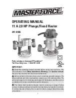
241-0836
Brand: MasterForce Pages: 12

RTR18
Brand: Ryobi Pages: 84
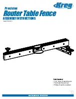
PRS1010
Brand: Kreg Pages: 24
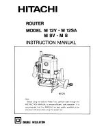
M 12V
Brand: Hitachi Pages: 19


