REVIEW DRAFT — CISCO CONFIDENTIAL
Cisco Small Business Pro
SRP521 Services Ready Platform VoIP Gateway
ADMINISTRATION
GUIDE
Page 1: ...REVIEW DRAFT CISCO CONFIDENTIAL Cisco Small Business Pro SRP521 Services Ready Platform VoIP Gateway ADMINISTRATION GUIDE ...
Page 2: ...isco IOS Cisco Press Cisco Systems Cisco Systems Capital the Cisco Systems logo Cisco Unity Collaboration Without Limitation EtherFast EtherSwitch Event Center Fast Step Follow Me Browsing FormShare GigaDrive HomeLink Internet Quotient IOS iPhone iQuick Study IronPort the IronPort logo LightStream Linksys MediaTone MeetingPlace MeetingPlace Chime Sound MGX Networkers Networking Academy Network Reg...
Page 3: ...izard 12 Chapter 3 Setting up the Interfaces of the Gateway 14 Setting up the WAN Interface 14 Internet Setup 14 Mobile Network 16 Connection Recovery 19 Setting up the LAN Interface 22 DHCP Server Pool Setting 22 Bridge VLAN Setting 26 Port Setting 28 Setting up the Wireless LAN 29 Basic Wireless Settings 29 Wireless Protected Setup 32 WPS Method 1 32 WPS Method 2 32 WPS Method 3 33 Wireless Secu...
Page 4: ... 50 Single Port Forwarding 51 Port Range Forwarding 53 Port Range Triggering 54 ALG Control 56 QoS 56 Bandwidth Control 56 QoS Policy 57 QoS Settings 57 Firewall 59 Firewall Filter 59 Internet Access Control 61 PPPoE Relay 64 DDNS 65 IGMP 69 UPnP 70 CDP Setting 71 Chapter 5 Voice Settings 73 Info 73 System 74 Chapter 6 Configuring VPN 75 IKE Policy 75 IPSec Policy 77 GRE Tunnel 80 ...
Page 5: ...NMP 91 Local TFTP 92 Time Setup 93 User List 95 Log 96 Factory Defaults 97 Firmware Upgrade 98 Backup Restore 99 Backup Configuration 99 Restore Configuration 100 Reboot 101 Chapter 8 Using Gateway Diagnostics 103 Ping Test 103 Traceroute Test 104 Chapter 9 Viewing the Gateway Status 106 Router Settings 106 Firewall Status 108 Interface Information 110 Wireless Client Information 111 Mobile Networ...
Page 6: ...Gateway Administration Guide 6 REVIEW DRAFT CISCO CONFIDENTIAL Contents QoS status 116 Routing table 117 ARP Table 119 CDP Neighbor Information 120 Appendix A Where to Go From Here 121 Appendix B Specifications 123 ...
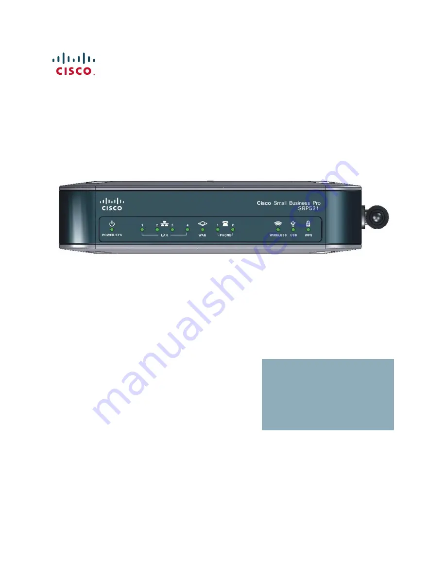
Page 7: ... Business Pro SRP521Services Ready Platform VoIP Gateway The gateway has the features needed for small business Its WAN port and four LAN ports support 10 100 Mbps speeds it has two ports to connect to analog telephone Service PSTN and supports 802 11b g n wireless networking Product Overview The SRP521 a member of the Cisco Small Business Pro family is a unified communications solution for small ...
Page 8: ...h indicates link traffic WAN Solid green indicates link Green flash indicates link traffic WIRELESS Solid green indicates the radio is operational Green flash indicates wireless traffic USB Solid green indicates USB device is operational Green flash indicates device failure or unsupported device WPS Solid green indicates WiFi Protected Setup success Slow green flash indicates setup in progress Fas...
Page 9: ...rk PSTN which is the analog telephone service network that traditional phone service uses WAN Port Use this port to connect the SRP521 to your WAN or DSL Internet connection LAN Ports 1 to 4 Use these ports to connect to a network device On Off Switch Use this switch to power the SRP521 on or off 12 V DC Power Use this port to connect the power adapter 276375 12VDC LAN 10 100 WAN 10 100 2 1 1 2 3 ...
Page 10: ...ls Feature Description RESET Button Press this button for 10 seconds to reset the SRP521 USB Port Use this port to connect a compatible 3G USB device For a list of compatible 3G USB modems please check the support community at cisco com go smallbizsupport Antenna SRP521 Wi Fi antenna 276380 USB RESET Reset button USB connector 276381 ...
Page 11: ...View Feature Description WPS Button To automatically configure wireless security for devices that support Wi Fi Protected Setup WPS press and hold this button until the WPS LED blinks NOTE The device being configured by WPS should be physically close to the SRP521 because Wi Fi power is reduced during the setup 276378 WPS Button ...
Page 12: ...etwork and provide personal network settings Many of the steps contains hyperlinks that quickly take you to that highlighted item STEP 1 Click Home on the tab and then click Quick Setup in the navigation pane The Quick Steup page appears STEP 2 Optionally you can click a hyperlink to jump to that page Starting the Setup Wizard The Setup Wizard guides you through the basic steps required to configu...
Page 13: ...P Gateway Administration Guide 13 2 REVIEW DRAFT CISCO CONFIDENTIAL STEP 1 Click Home on the tab and then click SetupWizard in the navigation pane The Setup Wizard page appears STEP 2 Follow the instructions in the Setup Wizard to configure your gateway ...
Page 14: ...can configure the gateway and get it working properly by using only the settings on these pages NOTE After you configure interfaces settings you should set a new password for the gateway using the Adminstration Access Setting page This precaution increases security protecting the gateway from unauthorized changes All users who try to access the web based Configuration Utility will be prompted for ...
Page 15: ... computer click the Clone Your PC s MAC button STEP 5 Click Submit to save your settings Field Description WAN Interface List The WAN Interface list which shows the physical link its protocol and itsIP address if one exists In each entry you can create new sub interface by clicking the Add Subinterface button or the Edit button If you have more than one sub interface you can choose ether one as th...
Page 16: ...N Flow Control WAN flow control To set flow control for the WAN select Enabled and click Submit The default setting is Disabled WAN Speed Duplex WAN Speed Duplex mode Selections are Auto negotiate 10 Half 10 Full 100 Half and 100 Full To set WAN speed duplex mode choose the mode and click Submit The default setting is Auto negotiate MAC Address Clone A MAC address is a 12 digit code assigned to a ...
Page 17: ...up the WAN Interface SRP 521 VoIP Gateway Administration Guide 17 3 REVIEW DRAFT CISCO CONFIDENTIAL NOTE You must click the Manual option in the Configure Mode field to manually setup your mobile network card STEP 4 Click Submit to save your settings ...
Page 18: ...erminated connection when a user attempts to access the Internet again In the Max Idle Time field enter the number of minutes of inactivity that can elapse before your Internet connection terminates The default is 5 minutes The gateway periodically checks your Internet connection If you are disconnected then it will automatically re establish your connection To use this option select Keep Alive In...
Page 19: ...mobile device is connecting to Enter the access point name provided by your mobile network service provider Dial Number The dial number for the Internet connection Enter the Dial Number provided by your mobile network service provider User Name Password Enter the user name and password provided by your mobile network service provider SIM PIN The PIN code associated with your SIM card Enter your SI...
Page 20: ...ace to the highest priority Enabling this feature also enables the Interface Connection Failover feature Whenever the Internet connection fails the gateway automatically attempts to bring up the mobile network connection on the USB interface if available Whenever the Ethernet Internet connection recovers the gateway automatically attempts to bring back and recover the Ethernet Internet connection ...
Page 21: ...nected when available Interface Connection Failover Failover detection works by detecting the physical connection and or presence of traffic on the Internet link If the link is idle the gateway attempts to ping a destination If the ping does not reply the gateway assumes the link is down and attempts to fail over to another interface Timeout The time interval at which the gateway detects the statu...
Page 22: ... to open the DHCP Add page From this page you can add a DHCP entry STEP 4 Click Submit to save your settings Failover Validation Site A ping target for the gateway to use to detect the status of the Internet connection By default the gateway pings the Network Time Protocol NTP servers You may specify a different IP address as a target here WAN Interfaces This area provides information on current s...
Page 23: ...ing up the LAN Interface SRP 521 VoIP Gateway Administration Guide 23 3 REVIEW DRAFT CISCO CONFIDENTIAL Click one of the items in the DHCP List DHCP information displays in the Details of DHCP table When you click Add Rule the DHCP Add page opens ...
Page 24: ...Name The DHCP Name Local IP Address Subnet Mask The DHCP IP address and subnet mask as seen by external users on the Internet including your ISP DHCP Server The DHCP server status DHCP is enabled by factory default If you already have a DHCP server then select Disable no other DHCP features will be available WAN Interface The WAN Interface ...
Page 25: ...aximum number of PCs that you want the DHCP server to assign IP addresses This number cannot be greater than 253 The default is 50 IP Address Range The range of DHCP addresses is displayed here Client Lease Time Amount of time a network user will be allowed connection to the gateway with their current dynamic IP address Enter the amount of time in minutes that the user will be leased this dynamic ...
Page 26: ...cking Add Rule you can create another VLAN STEP 1 Click Interface Setup on the tab and then click LAN in the navigation pane Click Bridge VLAN Setting The Bridge VLAN Setting page appears STEP 2 You can edit or delete a VLAN entry by clicking the edit or delete icon STEP 3 Click Add Rule to open the VLAN Add page From this page you can add a VLAN entry STEP 4 Click Submit to save your settings ...
Page 27: ...dge or VLAN ID Enable STP If you want to use Spanning Tree Protocol STP click this box Enable Voice Click this box if you want to use voice Only use this option in VLAN mode Address Type Address type Choices are None Static IP Address Dynamic IP Address and DHCP Server Pool The default value is None Available Interface The interfaces that are available to you Added Interface The interfaces that ar...
Page 28: ...Interface Setup on the tab and then click LAN in the navigation pane Click Port Setting The Port Setting page appears STEP 2 You can edit a port entry by clicking the edit icon After you click the edit icon the Port Edit page opens Make any necessary changes and click Submit to save your settings STEP 3 If necessary change the flow control or duplex speed settings for each interface STEP 4 Click S...
Page 29: ...less adapter s documentation STEP 1 Click Interface Setup on the tab and then click WiFi Setting in the navigation pane The Basic Wireless Settings page appears STEP 2 From the Network Mode menu you can select the wireless standards running on your network If you have Wireless N Wireless G and Wireless B devices in your network use the default setting Mixed If you have only Wireless G and Wireless...
Page 30: ...ices in your network select Disabled STEP 3 From the Radio Band menu you can select the wireless bandwidth on your network There are three options you can select Auto Standard 20MHz Channel and Wide 40MHz Channel STEP 4 Click Submit to save your settings Field Description Network Mode The network mode the default mode is Mixed Radio Band The bandwidth of the radio channel The default is Standard 2...
Page 31: ...less network The gateway can support up to four wireless networks By default first and second wireless network is enabled and you can create the other wireless network names Wireless Network Name SSID The first default wireless network uses the name cisco_data which is connected to the default VLAN The second default wireless network uses the name cisco_voice which is connected to the voip VLAN To...
Page 32: ...ings you want to configure STEP 3 In the WPS field select Disabled if you do not want to use the WiFi Protected Setup NOTE There are three methods available to configure your WiFi settings using WPS Use the method below that applies to the client device you are configuring WPS Method 1 Use this method if your client device has a Wi Fi Protected Setup button STEP 1 Click or press the Wi Fi Protecte...
Page 33: ...er instructions WPS Method 3 Use this method if your client device asks for the PIN number of the gateway STEP 1 Enter the PIN number listed on this page It is also listed on the label on the bottom of the gateway STEP 2 After the client device has been configured click OK Then refer to your client device or its documentation for further instructions The Wi Fi Protected Setup Status Network Name S...
Page 34: ...g up the Wireless LAN 34 SRP 521 VoIP Gateway Administration Guide 3 Field Description Select a SSID Choose the SSID for the wireless network that you want to configure The default is SSID1 WPS WiFi Protected Setup WPS option The default is Enabled ...
Page 35: ... stands for Wired Equivalent Privacy STEP 1 Click Interface Setup on the tab and then click WiFi Setting in the navigation pane Click Wireless Security The Wireless Security page appears STEP 2 From the Select a SSID menu choose the SSID for the wireless network that you want to configure STEP 3 Select the security method for your wireless network If you do not want to use wireless security use th...
Page 36: ...nal WPA Algorithms WPA supports two encryption methods TKIP and AES with dynamic encryption keys Select the type of algorithm AES or TKIP The default is TKIP WPA Shared Key The Passphrase of 8 63 characters Group Key Renewal The Key Renewal period which instructs the gateway how often it should change the encryption keys The default Group Key Renewal period is 3600 seconds WPA2 Personal WPA Algori...
Page 37: ...t The key shared between the gateway and the server RADIUS Server Address The IP address of the RADIUS server RADIUS Port The port number of the RADIUS server Shared Secret The key shared between the gateway and the server Key Renewal Timeout The Key Renewal period which instructs the gateway how often it should change the encryption keys The default Key Renewal period is 3600 seconds WPA2 Enterpr...
Page 38: ...he Access Restriction area select either Prevent or Permit RADIUS Port The port number of the RADIUS server The default value is 1812 Shared Secret The key shared between the gateway and the server Secondary RADIUS Server RADIUS Server Address The IP Address of the RADIUS server RADIUS Port The port number of the RADIUS server Shared Secret The key shared between the gateway and the server Key Ren...
Page 39: ...e Wireless Client List page This page shows computers and other devices on the wireless network The list can be sorted by Client Name Interface IP Address MAC Address and Status STEP 6 Select Save to MAC Address Filter List for any device you want to add to the list Then click Add To retrieve the most up to date information click Refresh To exit this page and return to the Wireless MAC Filter page...
Page 40: ... flow enter only minor reductions The default value of 2346 is recommended Field Description Select a SSID The MAC filter settings to apply to the SSID The default is SSID1 Enabled Disabled The option to filter wireless users by MAC Address Access Restriction Prevent Select this option to prevent devices with the MAC address in the table from accessing the wireless network This button is selected ...
Page 41: ... RTS frames to a particular receiving station and negotiates the sending of a data frame After receiving an RTS the wireless station responds with a Clear to Send CTS frame to acknowledge the right to begin transmission STEP 4 Change any settings in the Advanced Wireless for group SSID area STEP 5 Click Submit to save your settings Field Description Advanced Wireless for separate SSID Select a SSI...
Page 42: ...of rates at which the gateway can transmit The gateway advertises its Basic Rate to the other wireless devices in your network so they know which rates will be used The gateway will also advertise that it will automatically select the best rate for transmission The default setting is Default when the gateway can transmit at all standard wireless rates 1 2 Mbps 5 5 Mbps 11 Mbps 18 Mbps and 24 Mbps ...
Page 43: ...t is Auto DTIM Interval This value between 1 and 255 indicates the interval of the Delivery Traffic Indication Message DTIM A DTIM field is a countdown field informing clients of the next window for listening to broadcast and multicast messages When the gateway has buffered broadcast or multicast messages for associated clients it sends the next DTIM with a DTIM Interval value Its clients hear the...
Page 44: ...ck WMM Setting The WMM Setting page appears STEP 2 If you have other devices on your network that support WMM Support you can select Enabled for the WMM Support option STEP 3 In the No Ackowledgement option select Enabled to disable the acknowledgement feature so the gateway will not resend data if an error occurs STEP 4 Click Submit to save your settings Power Control The WiFi output power from t...
Page 45: ...ars STEP 2 Click on the loopback icon to change the IP address and subnet mask for each loopback interface The Loopback Interface page opens STEP 3 Enter the IP Address and Subnet Mask for each interface STEP 4 Click Submit to save your settings Field Description WMM Support If you have other devices on your network that support WMM Support select Enabled Otherwise use the default setting Disabled...
Page 46: ...ng up the Interfaces of the Gateway Using the Loopback Interface 46 SRP 521 VoIP Gateway Administration Guide 3 Field Description IP Address Subnet Mask The IP address and subnets for the loopback interfaces ...
Page 47: ...tting page 71 Static Routing These features are used to set up advanced functions of the gateway Dynamic Routing automatically adjusts how packets travel on your network Static Routing sets up a fixed route to another network destination Static Route Rule The settings for Static Route Rule are set on this page It shows the current static routing list and details of the selected route STEP 1 Click ...
Page 48: ...RP 521 VoIP Gateway Administration Guide 4 STEP 3 Enter a static route name destination IP address subnet mask and gateway IP address STEP 4 Click Submit to save your settings After clicking the Add Rule button the Static Routing Add page opens ...
Page 49: ...e the default setting Disabled STEP 3 Select the RIP version STEP 4 Set RIP timer values STEP 5 In the RIP List select the Interface that you want to enable the RIP function Or you can add the network address to join the RIP STEP 6 Click Submit to save your settings Field Description Enter Route Name The Static Routing Name Destination LAN IP The address of the network or host to which you want to...
Page 50: ...g to different VLANs to route to each other If disabled communications between hosts that belong to different VLAN are blocked Select either Enabled or Disabled and then Submit to enable or disable Intervlan routing NAT Setting The Routing page allows you to enable or disable NAT routing which allows the gateway to host your network connection to the Internet Enabled mode is recommended for most u...
Page 51: ... port forwarding list and details of the selected route STEP 1 Click Network Setup on the menu bar and then click NAT Click Single Port Forwarding The Single Port Forwarding page appears STEP 2 Click Add Rule The Single Port Forwarding page opens STEP 3 Select an application from the list STEP 4 Enter a name of the application STEP 5 Select a WAN interface STEP 6 Choose an external and internal po...
Page 52: ... by the server or Internet application Check with the Internet application documentation for more information Internal Port The internal port number used by the server or Internet application Check with the Internet application documentation for more information Protocol Select the protocol TCP or UDP or select Both IP Address The IP address of the server that should receive the requests Enable Cl...
Page 53: ...ab and then click NAT in the navigation pane Click Port Range Forwarding The Port Range Forwarding page appears STEP 2 Click Add Rule The Port Range Forwarding page opens STEP 3 Enter a name of the application STEP 4 Select a WAN interface STEP 5 Enter a starting and ending range STEP 6 Select a protocol STEP 7 Enter the IP address of the server that you want the Internet users to be able to acces...
Page 54: ...EP 5 Select a LAN interface STEP 6 Enter a triggered port range STEP 7 Enter a forwarded port range STEP 8 Click Enabled to enable the applications you have defined STEP 9 Click Submit to save your settings Field Description Application Name The name of the application WAN Interface Name List of WAN interface Start End Port The number or range of port s used by the server or Internet application C...
Page 55: ...red Range The starting and ending port numbers of the triggered port range Check with the Internet application documentation for the port number s needed Forwarded Range Enter the starting and ending port numbers of the forwarded port range Check with the Internet application documentation for the port number s needed Enable Click Enabled to enable the applications you have defined This is disable...
Page 56: ...l allows the gateway to control the maximum bandwidth for upstream data transmissions STEP 1 Click Network Setup on the tab and then click QoS in the navigation pane Click Bandwidth Control The Bandwidth Control page appears STEP 2 Click Enabled to enable bandwidth control Click Disabled to disable bandwidth control Bandwidth control is enabled by default at 50 000 Kbps STEP 3 If you enabled bandw...
Page 57: ... opens STEP 3 Enter a name of the application device or port name STEP 4 Choose a category type STEP 5 Select a LAN interface STEP 6 Enter a port range STEP 7 In the Priority menu choose the QoS priority STEP 8 Click Submit to save your settings QoS Settings Quality of Service QoS ensures better service to high priority types of network traffic Field Description Status The status for this feature ...
Page 58: ...ct one of the following Applications MAC Address Ethernet Port or VLAN LAN The LAN interface for this setting Port Range The number or range of port s used by the server or Internet application Check with the Internet application documentation for more information Select the protocol TCP or UDP or Both Priority The priority of this QoS setting Choices of bandwidth priority are High Medium Normal o...
Page 59: ...navigation pane Click Firewall Filter The Firewall page appears STEP 2 Select Enabled to enable firewall protection STEP 3 Click the Filter Anonymous Internet Requests option to keep your network from being pinged or detected by other Internet users STEP 4 Click Filter Internet NAT Redirection to block access to local servers from local networked computers STEP 5 Click Filter IDENT Port 113 to kee...
Page 60: ...Both make it more difficult for outside users to enter your network This filter is enabled by default Select Disabled to allow anonymous Internet requests Filter Internet NAT Redirection This feature uses port forwarding to block access to local servers from local networked computers Select Enabled to filter Internet NAT redirection or Disabled to disable this feature Filter IDENT Port 113 This fe...
Page 61: ... address policies STEP 8 Select other blocking options as necessary STEP 9 Click Submit to save your settings Proxy Use of WAN proxy servers may compromise the security of the gateway Denying Filter Proxy will disable access to any WAN proxy servers To enable proxy filtering click the box Java Java is a programming language for websites If you deny Java you run the risk of not having access to Int...
Page 62: ...Configuring the Network Firewall 62 SRP 521 VoIP Gateway Administration Guide 4 Field Description Enter Policy Name The Internet policy name ...
Page 63: ...sites with specific keywords Enter each Blocking by URL Website Blocking Keyword You can also block websites by specifying keywords in the URLs Enter each keyword in a separate field next to Website Blocking by Keyword Blocked Application You can filter access to various Internet services such as FTP or telnet You can block up to three applications per policy From the Applications list select the ...
Page 64: ...ows the LNS or tunnel switch to advertise the services it offers to the client thereby providing end to end control of services between the LNS and a PPPoE client The settings for PPPoE relay are set on this page After clicking Add Rule button the PPPoE Relay page opens STEP 1 Click Network Setup on the tab and then click PPPoE Relay in the navigation pane The PPPoE Relay page appears STEP 2 Click...
Page 65: ...re you can use this feature you need to sign up for DDNS service at www dyndns org or www tzo com DDNS service providers STEP 1 Click Network Setup on the tab and then click DDNS in the navigation pane The DDNS page appears STEP 2 Choose a DDNS service STEP 3 Enter the data for the service that you chose STEP 4 Click Submit to save your settings Field Description WAN option The WAN interface optio...
Page 66: ...must sign up for an account with DynDNS and TZO org before you can use this service Click Submit to save your choice the DynDNS or TZO pages open This feature is disabled by default Field Description User Name The user name from DynDNS org Password The password from DynDNS org Host Name Your host name This should be in the format of name dyndns org ...
Page 67: ...abled To disable this feature select Disable if you are not sure which seting to select use the default setting Enabled Wildcard This setting enables or disables wildcard for your host For example if your DDNS address is myplace dyndns org and you enable wildcard then the x myplace dyndns org will work as well x is the wildcard To enable wildcards use the default setting Enabled To disable wildcar...
Page 68: ...cription E mail Address The E mail Addres from TZO account TZO Key The key from TZO account Domain Name Your host name This should be in the format of name tzo org Internet IP Address Your current IP address Status Your DDNS status Update To manually trigger an update click this button ...
Page 69: ... the IGMP feature of the gateway STEP 1 Click Network Setup on the tab and then click IGMP in the navigation pane The IGMP page appears STEP 2 Select the version you want to support IGMP v1 IGMP v2 or IGMP v3 If you are not sure which version to select use the default setting IGMP v2 STEP 3 If you want to allow multicast traffic through the gateway for your multimedia application devices use the d...
Page 70: ...erwise use the default setting Enabled STEP 4 To keep UPnP configuration settings after system reboot click Enabled STEP 5 To prohibit any and all Internet connections click Enabled STEP 6 Click Submit to save your settings Field Description Support IGMP Version Select the version you want to support IGMP v1 IGMP v2 or IGMP v3 If you are not sure which version to select use the default setting IGM...
Page 71: ...P If you want to use UPnP use the default setting Enabled Otherwise select Disabled Allow Users to Configure If you do not want to be able to make manual changes to the gateway while using the UPnP feature select Disabled Otherwise use the default setting Enabled Keep UPnP Configurations After System Reboot This choice will decide to save UPnP configuration after system reboot The default is disab...
Page 72: ...tion pane The CDP Setting page appears STEP 2 Select CDP options STEP 3 Select CDP Setting per Ethernet port STEP 4 Click Submit to save your settings Field Description CDP CDP options Enable All Disabled All and Per Port The default is Per Port CDP Timer The CDP timer The CDP timer range is 5 900 CDP Hold Timer The CDP Hold timer The CDP timer range is 10 255 ...
Page 73: ...tion Guide 73 REVIEW DRAFT CISCO CONFIDENTIAL Voice Settings This chapter describes how to administer and view voice settings Info page 73 System page 74 Info The Info page provides information about the product system and line status ...
Page 74: ...Voice Settings System 74 SRP 521 VoIP Gateway Administration Guide 5 System The System page lets you set a password for system configuration for voice ...
Page 75: ...different VPN policies Clicking the Add Rule button opens the IKE Policy Configuration page STEP 1 Click VPN on the tab and then click Site to Site IPSec VPN in the navigation pane Click IKE Policy The IKE Policies page appears STEP 2 Click Add Rule The IKE Policy Configuration page opens STEP 3 In the Policy Name field enter a unique name used for the VPN policy STEP 4 Select an Exchange mode STE...
Page 76: ...al Policy Name Unique name used for the VPN policy Exchange Mode Main or Aggressive mode selection IKE SA Parameters Encryption Algorithm Encryption algorithms in IKE SA Choices are DES 3DES AES128 AES192 or AES256 Authentication Algorithm Authentication algorithm in IKA SA Choices are MD5 and SHA1 ...
Page 77: ...the VPN policy STEP 5 Select a policy type STEP 6 Enter the remote gateway information with which you are going to connect to establish a IPSec VPN tunnel STEP 7 Choose an encryption algorithm Diffie Hellman DH Group DH Group option Choices are Group 1 768 bits or Group 2 1024bits Enable Dead Peer DPD Detection This function is not necessary for an IKE rule but it will help to keep connection aliv...
Page 78: ...licy 78 SRP 521 VoIP Gateway Administration Guide 6 STEP 8 Choose an integrity algorithm STEP 9 Enter auto policy parameters STEP 10 Enter local and remote traffic selection settings STEP 11 Click Submit to save your settings ...
Page 79: ...o establish a IPSec VPN tunnel Your choices are IP Address Any or FQDN The Any option will only appear in Auto Policy and is available to increase security level for roaming users The FQDN option requires a Full Qualified Domain Name Ensure that the domain name can be resolved into IP address by a correct DNS server if the VPN tunnel can not be established Encryption Algorithm Encryption algorithm...
Page 80: ...TEP 4 Enter a name for the tunnel STEP 5 Set the Checksum Sequence and Key parameters STEP 6 Enter destination IP address of the remote network or host to which you want to build a tunnel Encryption Algorithm Key A HEX value the length depends on the key type of Encryption Algorithm above For example 3DES length is 32 Integrity Algorithm Key A HEX value the length depends on the key type of Integr...
Page 81: ...AL STEP 7 Enter the IP address and subnet mask of the remote host You can use the Add button to add additional addresses STEP 8 Click Submit to save your settings Field Description Number The tunnel number that you are going to configure Status The status of the tunnel Tunnel Name The name of the tunnel ...
Page 82: ...th Input and Output sequencing The default is None Key From this drop down menu choose None Both Input and Output value The Input parameter sets the key for input The Output parameter sets the key for output The Both parameter sets the key to use in both directions The default is None Key value The key value The Key Value must be number is between 0 and 4294967295 WAN Interface The WAN subinterfac...
Page 83: ...tion pane Click VPN Passthrough The VPN Passthrough page appears STEP 2 To enable IPSec passthrough click Enabled STEP 3 To enable PPTP passthrough click Enabled STEP 4 To enable L2TP passthrough click Enabled STEP 5 Click Submit to save your settings Field Description IPSec Passthrough Internet Protocol Security IPSec is a suite of protocols used to implement secure exchange of packets at the IP ...
Page 84: ...ocol PPP to be tunneled through an IP network PPTP Pass Through is enabled by default To disable PPTP Passthrough select Disabled L2TP Passthrough Layer 2 Tunneling Protocol is the method used to enable Point to Point sessions via the Internet on the Layer 2 level L2TP Pass Through is enabled by default To disable L2TP Passthrough select Disabled Field Description ...
Page 85: ...irmware Upgrade page 98 Backup Restore page 99 Reboot page101 Web Access Management You can configure access settings and remote acess rules from the Web access management features Settings This page allows you to change the access settings of the gateway STEP 1 Click Administration on the tab and then click Web Access Management in the navigation pane Click Setting The Access Setting page appears...
Page 86: ...ration Guide 7 STEP 4 Select Web Access options STEP 5 Select Remote Access options STEP 6 Click Submit to save your settings Field Description Router Access Router Password The new password for the gateway Re enter to confirm The new Password entered a second time to confirm it ...
Page 87: ... IP address select Any IP Address If you want to specify an external IP address or range of IP Web Access Web Utility Access To access this web utility you can have no security HTTP or security HTTPS For HTTPS enter https xxx xxx xxx xxx the x s represent the gateway s Internet IP address in your web browser s Address field Web Utility Access via Wireless This option specifies whether an administr...
Page 88: ...the fields provided STEP 8 Click Submit to save your settings Field Description WAN The WAN interface WAN Remote Management Port The port number that will open the WAN access LAN The LAN interface LAN Remote Management Port The port number that will open the LAN access Allowed Remote IP Address The allowed remote IP address or range of addresses ...
Page 89: ...ment in the navigation pane Click TR 069 The TR 069 page appears STEP 2 Click Enabled to enable TR 069 STEP 3 Enter the URL for ACS The format should be http s xxx xxx xxx xxx port or xxx xxx xxx xxx port The xxx xxx xxx xxx is domain name or IP of ACS server and after is port Both IP and port must be filled STEP 4 Enter the ACS username and password STEP 5 Enter the Connection request username an...
Page 90: ...me or IP of ACS server and after is port Both IP and port must be filled ACS Username The username for ACS The default username is OUI Serial Number this should be the same as configured at ACS side and must be filled ACS Password The password for ACS This should be the same as configured at ACS side and must be filled ConnectionRequest URL This field will be auto filled and does not need to be fi...
Page 91: ... STEP 3 Choose a trusted IP setting STEP 4 Click Submit to save your settings ConnectionRequest Username Connection request username This should be the same as configured at ACS side ConnectionRequest Password Connection request password This should be the same as configured at ACS side Periodic Inform Interval The periodic inform interval The default value is 86400 seconds Periodic Inform Enable ...
Page 92: ...2 Click Enabled to enable TFTP STEP 3 Click Submit to save your settings Field Description Enable Disable To enable SNMP identification click Enabled To disable SNMP click Disabled Trusted IP Only trusted IP or IP range can access this gateway via SNMP Get Community Enter the password that allows read only access to the SNMP information of the gateway Set Community Enter the password that allows r...
Page 93: ... adjust clock for daylight saving changes option if you want the gateway to automatically adjust for daylight saving time STEP 4 If you want to use the default Network Time Protocol NTP server use the default setting Auto If you want to specify the NTP server select Manual and enter the URL or IP address of the NTP server you want to use STEP 5 The Resync timer controls how often the gateway resyn...
Page 94: ...teway to automatically adjust for daylight saving time This option is enabled by default Time Server Address If you want to use the default Network Time Protocol NTP server use the default setting Auto If you want to specify the NTP server select Manual and enter the URL or IP address of the NTP server you want to use Resync Timer The timer controls how often the gateway resyncs with the NTP serve...
Page 95: ...icking the Add Rule button opens the User Add page STEP 1 Click Administration on the tab and then click User List in the navigation pane The User List page appears STEP 2 Click Add User STEP 3 Enter a new Username STEP 4 Enter a password STEP 5 Re enter the password to confirm it STEP 6 Select administrative power of the new user STEP 7 Click Submit to save your settings ...
Page 96: ...Click Administration on the tab and then click Log in the navigation pane The Log page appears STEP 2 Click Enabled to enable logging STEP 3 Choose the log type from the Log List area STEP 4 Click Apply to save your settings Field Description Username The new Username Password To ensure the security of the gateway you will be asked for your password when you access the Web based Utility The defaul...
Page 97: ...vigation pane The Factory Defaults page appears STEP 2 Click Yes in the Restore Router Factory Defaults to restore the gateway to its factory defaults STEP 3 Click Yes in the Restore Voice Factory Defaults to restore the voice settings to factory defaults Field Description Status To access activity logs select Enabled With logging enabled you can view temporary logs Click Disabled to disable this ...
Page 98: ...Restore Router Factory Defaults To reset the gateway settings to the default values select Yes Then click Submit Any custom gateway settings you have saved will be lost when the default settings are restored Restore Voice Factory Defaults To reset the voice settings to the default values select Yes Then click Submit Any custom Voice settings you have saved will be lost when the default settings ar...
Page 99: ...s STEP 2 Enter the username and password provided by your service provider STEP 3 Click OK to upgrade the gateway Backup Restore Backup Configuration The Backup Configuration feature lets you to backup the configuration settings of the gateway to a file which you can use later to restore the gateway to the same settings Field Description Username Username provided by the service provider User Pass...
Page 100: ...estore Configuration feature lets you restore the gateway to configuration settings from a previous backup session STEP 1 Click Administration on the tab and then click Backup Restore in the navigation pane Click Restore Configuration The Restore Configuration page appears STEP 2 Click Browse and select previously backed up configuration file STEP 3 Click Restore to restore the configuration of th...
Page 101: ...utility STEP 1 Click Administration on the tab and then click Reboot in the navigation pane The Reboot page appears STEP 2 Click Reboot to reboot the gateway Field Description Restore To restore the configuration settings of the gateway click Browse and locate a backup file and click Restore You must have previously backed up the configuration settings of the gateway ...
Page 102: ...Administration Settings Reboot 102 SRP 521 VoIP Gateway Administration Guide 7 Field Description Reboot Click Reboot to power cycle the gateway ...
Page 103: ...ing Test page103 Traceroute Test page104 Ping Test You can perform a ping test from the configuration utility STEP 1 Click Diagnostics on the tab and then click Ping Test in the navigation pane The Ping Test page appears STEP 2 Enter an IP or URL address STEP 3 Enter a packet size in bytes STEP 4 Select the number of times to ping STEP 5 Click Start to Ping to start the test ...
Page 104: ...ane The Traceroute Test page appears STEP 2 Enter an IP or URL address STEP 3 Click Start to Traceroute to start the test Field Description IP or URL Address The IP address or URL that you want to ping Packet Size The size of the packet you want to use The range is 32 to 65500 bytes Times to Ping Select the number of times you wish to ping 5 10 or Unlimited Start to Ping Click this button to begin...
Page 105: ...eway Administration Guide 105 8 REVIEW DRAFT CISCO CONFIDENTIAL Field Description IP or URL Address The IP address or URL that you want to do a trace route Start to Traceroute Click this button to begin the test A new page appears and displays the test results ...
Page 106: ...Interface Information page110 Wireless Client Information page111 Mobile Network page112 DHCP Server Information page115 QoS status page116 Routing table page117 ARP Table page119 CDP Neighbor Information page 120 Router Settings You can view various status parameters of the gateway from the configuration utility STEP 1 Click Status on the tab and then click Router in the navigation pane The Route...
Page 107: ... version number of the gateway Boot Version The current version number of the gateway Firmware Version The current firmware version number of the gateway Recovery Firmware The current recovery firmware version number of the gateway Current Time The time set on the gateway CPU CPU information MIPS Loads and Uptime of the gateway Memory Memory total size free size used size buffer size cached size a...
Page 108: ... You can view firewall status from the configuration utility STEP 1 Click Status on the tab and then click Firewall Status in the navigation pane The Firewall page appears WAN The WAN interface type and level LAN This show LAN interface and level Wireless This show Wireless SSID and level Field Description ...
Page 109: ...e in bytes Blocked pkts Packet blocked by this rule Blocked bytes Traffic volume blocked by this rule Single Port Forward Protocol TCP UDP or Both TCP and UDP Port User specified port to forward Host LAN host IP address to forward to Packets Number of packets that are forwarded Traffic bytes Traffic volume that are forwarded in bytes Port Range Forward Protocol TCP UDP or Both TCP and UDP Port Use...
Page 110: ... Status on the tab and then click Interface Information in the navigation pane The Interface Information page appears Accept PKT Number of packets that are accepted by this firewall chain Accept Volume bytes Traffic volume accepted by this firewall chain Drop PKT Number of packets that dropped by this firewall chain Drop Volume bytes Traffic volume dropped by this firewall chain Field Description ...
Page 111: ... navigation pane The Wireless Client Information page appears Field Description Interface List Interface The current VLAN interface including the LAN and WAN side Connect Type The kind of protocol to use apply on this interface IP Address The IP address of the interface Subnet Mask The subnet mask of the interface Port List Interface The current physical port TX pkts The number of packets transmit...
Page 112: ...ption MAC Address The MAC address of the station Tx Rate The current data rate of the association RSSI The signal strength of the last received packet For MIMO devices this is an average value over all active received chains IDLE The current setting of the station inactivity timer This is the time in milliseconds when the station will go into power save if no activity occurs on the link ...
Page 113: ...ile Network in the navigation pane The Mobile Network page appears If the USB 3G data card is UMTS Field Description IP Address IP address associated to this 3G connection Connection Up Time Time elapsed associated to this 3G connection Current session usage RX and TX traffic volume Manufacturer Manufacturer of this 3G data card Card Model Model name of this 3G data card ...
Page 114: ...is 3G data card SIM Status SIM card status SIM ready or pin code needed IMSI IMSI number of this 3G data card Service Type 3G service type Signal strength Signal strength Card status The status of the card Connecting Connected Disconnecting Disconnected or Card is not activated Field Description IP Address IP address associated to this 3G connection Field Description ...
Page 115: ...psed associated to this 3G connection Current session usage RX and TX traffic volume Manufacturer Manufacturer of this 3G data card Card Model Model name of this 3G data card Card Firmware Firmware revision of this 3G data card ESN ESN number of this 3G data card PRL Version PRL Version of this 3G data card Phone Number Phone Number associated with the account of 3G data card Carrier Carrier name ...
Page 116: ... priority constant rate and burst rate which are configurable STEP 1 Click Status on the tab and then click QoS Status in the navigation pane The QoS Status page appears Field Description Client Name The name of DHCP server IP Address The IP address of the DHCP server MAC Address The MAC address of the DHCP server Expires Time The expiry time of the DHCP server Interface The interface time of the ...
Page 117: ...mation from the configuration utility Field Description QoS Name Name of the QoS queue Allow Rate Allowed transmission rate Allow Ceil Allowed burst rate Send bytes Quantity of bytes sent Send pkts Quantity of packets sent Drop Number of packets dropped Overlimits Overlimits for this queue Requeues Requeues for this queue Current Rate bps Current rate of transmission ...
Page 118: ...the address of the network or host to which the static route is assigned Subnet Mask The Subnet Mask determines which portion of an IP address is the network portion and which portion is the host portion Gateway This is the IP address of the gateway device that allows for contact between the gateway and the network or host Interface This interface tells you whether the Destination IP Address is on...
Page 119: ...ormation from the configuration utility STEP 1 Click Status on the tab and then click ARP Table in the navigation pane The ARP Table page appears Field Description IP address IP address of the device HW type Hardware type of the device Flags Flag type of the device HW address MAC address of the device Mask Mask of the device Device Device interface type ...
Page 120: ...lick Status on the tab and then click Neighbor Information in the navigation pane The Neighbor Information page appears Field Description Device ID The device ID of the neighbor Local Interface The local gateway name Hold Time The hold time before which CDP will throw away packets Capability The class of the neighbor Port ID The port number of the neighbor IP Address The IP address of the neighbor...
Page 121: ...rt Contacts www cisco com en US support tsd_cisco_small_ business_support_ center_contacts html Software Downloads Login Required Go to tools cisco com support downloads and enter the model number in the Software Search box Product Documentation Cisco Small Business Pro Secure Router Series www cisco com en US products ps tsd_products_support_series_home html Cisco Small Business Cisco Partner Cen...
Page 122: ...Where to Go From Here Title 122 A REVIEW DRAFT CISCO CONFIDENTIAL ...
Page 123: ...ast Ethernet Ports Wireless 802 11b g n Operating Temperature 0 C to 40 C Storage Temperature 20 C to 70 C Operating Humidity 10 to 85 Non Condensing Storage Humidity 5 to 90 Non Condensing Voltage Range 100 240V 50 60Hz AC Dimensions W x D x H 170mm 6 69 inches x 170mm 6 69 inches x 42mm 1 65 inches ...