

Americas Headquarters
Cisco Systems, Inc.
170 West Tasman Drive
San Jose, CA 95134-1706
USA
http://www.cisco.com
Tel: 408 526-4000
800 553-NETS (6387)
Fax: 408 527-0883
Cisco, Cisco Systems, the Cisco logo, and the Cisco Systems logo are registered trademarks or
trademarks of Cisco Systems, Inc. and/or its affiliates in the United States and certain other
countries. All other trademarks mentioned in this document or Website are the property of their
respective owners. The use of the word partner does not imply a partnership relationship between
Cisco and any other company. (0705R)
78-xxxxx-xx
Rack Mount Instruction Tips
•
Ambient Temperature—To prevent the security appliance from
overheating, do not operate the security appliance in an area that exceeds
an ambient temperature of 104 degrees (40 C).
•
Size—The security appliance can be mounted in any standard size, 19-inch
wide rack. Each security appliance requires 1RU of space.
•
Reduced Air Flow—If you install the security appliance in a rack, be sure
that there is adequate air flow as required.
•
Mechanical Loading—Be sure that the security appliance is level and stable
when you mount the security appliance in a rack to avoid any hazardous
condition.
•
Circuit Overloading—Do not overload the power outlet or circuit when
installing multiple devices in a rack.
•
Reliable Grounding—Be sure that the security appliance is grounded and
use suitable electrical supply connections.
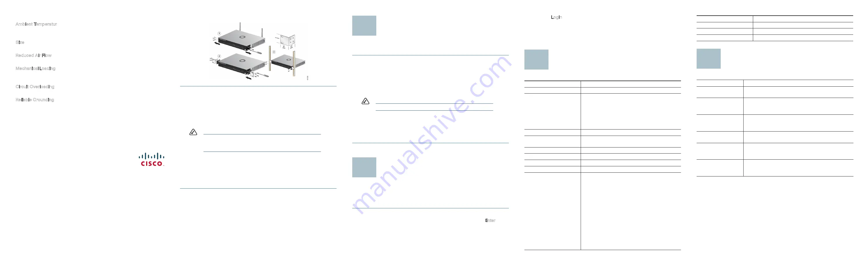
To use the rack-mount option, refer to the graphic and follow these instructions:
S
TEP
1
Remove the four screws from each side of the security appliance.
Retain the screws for re-installation.
S
TEP
2
Place one of the supplied spacers on the side of the Ethernet security
appliance so the four holes align to the screw holes.
S
TEP
3
Place a rack mount bracket next to the spacer and reinstall the four
screws removed in step 1.
N
OTE
If your screws are not long enough to reattach the bracket with the
spacer in place, attach the bracket directly to the case without the
spacer.
S
TEP
4
Using the supplied hardware, screw the mounting brackets into place
on both sides of the security appliance as shown.
S
TEP
5
After the mounting hardware has been securely attached, the security
appliance is now ready to be installed into a standard 19-inch rack as
shown.
Installation
Perform the steps in this section to install the hardware.
S
TEP
1
Connect the supplied power cord to an electrical outlet.
S
TEP
2
For end user devices, connect an Ethernet network cable to one of the
numbered ports on the security appliance. Connect the other end to a
computer or other network device.
S
TEP
3
For uplink devices, connect an Ethernet network cable to the WAN port
on the security appliance.
N
OTE
Cisco strongly recommends using Cat5e or better cable.
S
TEP
4
Power on the devices connected to the security appliance. Each active
port’s corresponding LED will light up on the security appliance.
Congratulations! The installation of the security appliance is complete!
Configuring the Security
Appliance
This section contains information for starting the configuration utility.
To start configuring the security appliance, follow these steps:
S
TEP
1
Open a web browser.
S
TEP
2
Enter the device’s IP address in the address bar and press Enter. The
Enter Network Password Page
opens:
S
TEP
3
Enter a user name and password. The default user name and
password are
cisco/cisco
. Passwords are both case sensitive and
alpha-numeric.
3
4
S
TEP
4
Click Login. The
Configuration Utility
Page opens.
Details about configuring the security appliance are found in the
SA5XX Series
Administration Guide
.
Specifications
n
o
i
t
a
c
i
f
i
c
e
p
S
m
e
t
I
Standards
IEEE 802.3, 802.3u, 802.3x, 802.3ab
x
1
,
N
A
W
x
1
,
s
t
r
o
p
s
p
b
G
1
5
4
-
J
R
x
4
:
0
2
5
A
S
s
t
r
o
P
optional for LAN/WAN/DMZ
SA520W: 4x RJ-45 1Gbps ports, 1x WAN, 1x
optional for LAN/WAN/DMZ
SA540: 8x RJ-45 1Gbps ports, 1x WAN, 1x
optional for LAN/WAN/DMZ
Cabling Type
Cat5 Ethernet
8
-
1
.
W
0
2
5
A
S
,
0
2
5
A
S
r
o
f
4
-
1
T
C
A
/
K
N
I
L
,
r
e
w
o
P
s
D
E
L
for SA540.
Security Feature
Security Slot
Dimensions
12.1” x 7.08” x 1.73” (308 mm x 180 mm x 44 mm)
Unit Weight
3.03 lbs. (1.376kg)
Power
AC 90V~264V
Certification
FCC/IC (USA/Canada) EMI: Part 15B/ICES-003
FCC (USA) ; Wireless, Part 15C
IC (Canada) ; Wireless, RSS-210
UL/cUL (USA/Canada) Safety: UL 60950-1
CE (Europe) EMI EN 55022, EN 55024, EN 60950-
1
CE (Europe) ; Wireless, EN 301 489 -1 & -17
, EN300 328
Frequency Authority for 28 Country
C-tick (Australia and New Zealand) AS/NZS
CISPR22
CB (worldwide) IEC6090-1
5
Where to Go From Here
Operating Temperature
0ºC to 40ºC (32ºF to 104ºF)
Storage Temperature
-20ºC to 70ºC (-4ºF to 158ºF)
Operating Humidity
10 to 90%, relative humidity, Non-Condensing
Storage Humidity
5% to 90% Non-Condensing
Resource
Location
Technical
Documentation
www.cisco.com/en/US/products/
ps#####
/
prod_maintenance_guides_list.html
Customer Support
www.cisco.com/en/US/support/
tsd_cisco_small_business_support_center_contacts.
html
Warranty and End
User License
Agreement
www.cisco.com/go/warranty
Open Source License
Notices
www.cisco.com/go/osln
Regulatory
Compliance and
Safety Information
www.cisco.com/en/US/products/
ps#####
/
prod_maintenance_guides_list.html
Cisco Partner Central
site for Small
Business
www.cisco.com/web/partners/sell/smb/
6


