Appendix A
Module Parameter Descriptions
110
78-4015908-01 Rev F
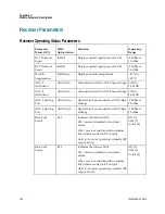
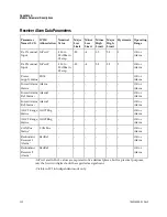
Receiver Configurable Parameters
Parameter
Name (LCI)
ICIM
Abbreviation
Description
Values
Default
-
-
NomPwr1
NomPwr2
Nominal Rx1 or Rx2 optical input
power level. Input power alarms
are calculated relative to this value.
Decimal number
between -18.0 and
2 dBm in
increments of
0.5 dBm
0 dBm
Mode Select
Mode
Module redundancy control. If set
to Master, the unit is only
controlled by the Enable control. If
set to Slave, the unit is controlled by
the Enable control and the external
input CNT_IN.
If set to Single, Rx1 and Rx2 will
continue to operate (i.e. not switch)
even if the optical input level falls
below the major alarm threshold.
If set to Independent, Rx1 and Rx2
are independently set to Master or
Slave mode by Mode1 and Mode2.
Single, Master,
Slave, or
Independent
Single
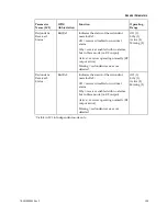
Rx 1 Receiver
Enable
Rx 2 Receiver
Enable
Enable1
Enable2
Enables or disables Rx1 or Rx2. If
set to Off, the receiver is muted (RF
amplifier turned off), alarms are
inhibited, and redundancy is turned
off.
OFF = Disabled
ON = Enabled
ON
Rx 1 Mute Switch
Rx 2 Mute Switch
Mute 1
Mute 2
Defines the initial status of the Rx1
or Rx2 RF Output mute control. If
On, the output is muted. However,
the alarm can override the initial
status and change the mute setting.
OFF = Mute Off
ON = Mute On
OFF
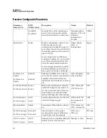
Rx 1 Attenuator
Rx 2 Attenuator
Attn1
Attn2
Sets the attenuation level of the Rx1
or Rx2 RF Output signal.
0 dB to 26.25 dB
in increments of
1.0 dB
0 dB
Manual Alarm
1
Alarm
Force alarm if the Enable control is
On.
ON = Alarm On
OFF = Alarm Off
OFF
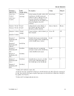
Rx 1 Wavelength
Rx 2 Wavelength
Wavelen1
Wavelen2
Selects the Rx1 or Rx2 optical
wavelength for proper calibration
of input power measurements.
1310 nm or
1550 nm
1310 nm
AGC 1 Control
AGC 2 Control
AGC1
AGC2
Enables (Auto) or disables (Manual)
the Rx1 or Rx2 AGC function.
Manual or Auto
Manual


