
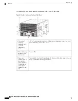


Rack and Cabinet Requirements
You can install the following types of racks or cabinets for your switch:
•
Standard perforated cabinets
•
Solid-walled cabinets with a roof fan tray (bottom to top cooling)
•
Standard open four-post Telco racks
To correctly install the switch in a cabinet that is located in a hot-aisle/cold-aisle environment, you should fit
the cabinet with baffles to prevent exhaust air from recirculating into the chassis air intake.
Work with your cabinet vendors to determine which of their cabinets meet the following requirements or see
the Cisco Technical Assistance Center (TAC) for recommendations:
•
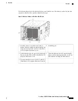
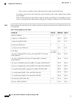
Use a standard 19-inch (48.3 cm), four-post Electronic Industries Alliance (EIA) cabinet or rack with
mounting rails that conform to English universal hole spacing per section 1 of the ANSI/EIA-310-D-1992
standard.
•
The height of the rack or cabinet must accommodate the 7.1-RU (12.4 inches or 31.6 cm) height of the
switch and its bottom support bracket.
•
The depth of a four-post rack must be 24 to 32 inches (61.0 to 81.3 cm) between the front and rear
mounting brackets.
•
Required clearances between the chassis and the edges of its rack or the interior of its cabinet are as
follows:
◦
4.5 inches (11.4 cm) between the front of the chassis and the front of the rack or interior of the
cabinet (required for cabling).
◦
3.0 inches (7.6 cm) between the rear of the chassis and the interior of the cabinet (required for
airflow in the cabinet if used).
◦
No clearance is required between the chassis and the sides of the rack or cabinet (no side airflow).
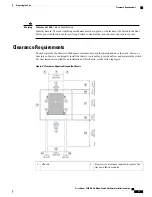
Additionally, you must consider the following site requirements for the rack:
•
Power receptacles must be located within reach of the power cords used with the switch.
Power cords for 3-kW AC power supplies are 8 to 12 feet (2.5 to 4.3 m) long. For the power cord
specifications, see
•
Clearance is required for cables that connect to as many as 192 ports (in addition to the cabling required
for other devices in the same rack). These cables must not block access to any removable chassis modules
or block airflow into or out of the chassis. Route the cables through the cable management frames on
the left and right sides of the chassis.
Cisco Nexus 9504 NX-OS Mode Switch Hardware Installation Guide
10
Preparing the Site
Rack and Cabinet Requirements