background image

Quantity

Description

Illustration

1 kit

Ground lug kit

Two-hole lug (1)

M4 x 8-mm Phillips pan-head screws (2)

1

Cable tie, 8.5 inches (10)

1

ESD wrist strap (disposable)

1

Hazardous substances list for customers in
China

Not applicable

1

Cisco Information Packet

Not applicable

1

1-Year Limited Warranty for Hardware

Not applicable

If you do not receive a part listed in this document, contact Cisco Technical Support at this URL:
http://www.cisco.com/warp/public/687/Directory/DirTAC.shtml.

If you purchased this product through a Cisco reseller, you might receive additional contents in your kit,
such as documentation, hardware, and power cables.

Note

The product shipment includes a power cord for each 3-kW AC power supply. You must supply a 6 AWG
cable for up to 45 A.

The shipped cables depend on your specification when placing an order. The available power cords for the
3-kW AC power supplies are as follows:

CAB-AC-16A-AUS

power cord, 250-VAC 16A, C19, Australia

   Cisco Nexus 9504 NX-OS Mode Switch Hardware Installation Guide

98

Accessory Kits

Accessory Kit Contents

Summary of Contents for Nexus 9504

Page 1: ...re Installation Guide First Published March 24 2014 Last Modified November 13 2014 Americas Headquarters Cisco Systems Inc 170 West Tasman Drive San Jose CA 95134 1706 USA http www cisco com Tel 408 526 4000 800 553 NETS 6387 Fax 408 527 0883 ...

Page 2: ...e encouraged to try to correct the interference by using one or more of the following measures Reorient or relocate the receiving antenna Increase the separation between the equipment and receiver Connect the equipment into an outlet on a circuit different from that to which the receiver is connected Consult the dealer or an experienced radio TV technician for help Modifications to this product no...

Page 3: ...equirements 5 Altitude Requirements 6 Dust and Particulate Requirements 6 Minimizing Electromagnetic and Radio Frequency Interference 6 Shock and Vibration Requirements 7 Grounding Requirements 7 Planning for Power Requirements 7 Rack and Cabinet Requirements 10 Clearance Requirements 11 C H A P T E R 3 Installing a Chassis 13 Installing a Rack or Cabinet 13 Unpacking and Inspecting a New Switch 1...

Page 4: ...the Installed Hardware Modules 35 Displaying the Hardware Inventory for a Switch 38 Displaying the Backplane and Serial Number Information 39 Displaying Environmental Information for the Switch 41 Displaying the Current State of a Module 42 Displaying Temperatures for a Module 44 Connecting to a Module 45 Saving the Module Configuration 46 Shutting Down or Starting Up a Module 47 Purging a Nonfunc...

Page 5: ...ng a Fabric Module 76 Installing a 3 kW AC Power Supply 78 A P P E N D I X A System Specifications 83 Environmental Specifications 83 Switch Dimensions 84 Weights and Quantities for the Chassis Modules Fan Trays and Power Supplies 84 Power Requirements for Switch Modules and Fan Trays 85 Maximum Power Available to the Switch 86 Transceivers Connectors and Cables 87 Transceiver and Cable Specificat...

Page 6: ...Power Supply LEDs 96 A P P E N D I X C Accessory Kits 97 Accessory Kit Contents 97 Cisco Nexus 9504 NX OS Mode Switch Hardware Installation Guide vi Contents ...

Page 7: ...ches Documentation Conventions Command descriptions use the following conventions Description Convention Bold text indicates the commands and keywords that you enter literally as shown bold Italic text indicates arguments for which the user supplies the values Italic Square brackets enclose an optional element keyword or argument x Square brackets enclosing keywords or arguments separated by a ver...

Page 8: ... in italic screen font italic screen font Nonprinting characters such as passwords are in angle brackets Default responses to system prompts are in square brackets An exclamation point or a pound sign at the beginning of a line of code indicates a comment line Related Documentation for Cisco Nexus 9000 Series NX OS Software The entire Cisco NX OS 9000 Series documentation set is available at the f...

Page 9: ...Nexus 7000 Series and 9000 Series NX OS MIB Quick Reference Cisco Nexus 9000 Series NX OS Programmability Guide Cisco Nexus 9000 Series NX OS Software Upgrade and Downgrade Guide Cisco Nexus 9000 Series NX OS System Messages Reference Cisco Nexus 9000 Series NX OS Troubleshooting Guide Cisco NX OS Licensing Guide Cisco NX OS XML Interface User Guide Hardware Documents Cisco Nexus 93128TX NX OS Mod...

Page 10: ... gathering additional information see the monthly What s New in Cisco Product Documentation which also lists all new and revised Cisco technical documentation at http www cisco com en US docs general whatsnew whatsnew html Open a service request online at https tools cisco com ServiceRequestTool create launch do Subscribe to the What s New in Cisco Product Documentation as a Really Simple Syndicat...

Page 11: ...0 Gigabit SFP plus 4 port 40 Gigabit QSFP I O module N9K X9464PX 48 port 1 10 GBASE T plus 4 port 40 Gigabit QSFP I O module N9K X9464TX 48 port 1 10 GBASE T plus 4 port QSFP I O module N9K X9564TX 48 port 1 10 Gigabit SFP plus 4 port QSFP I O module N9K X9564PX 36 port 40 Gigabit QSFP aggregation non blocking I O module N9K X9636PQ 36 port 40 Gigabit QSFP I O module N9K X9536PQ 32 port 40 Gigabit...

Page 12: ...4 4 Two vertical mounting brackets used to mount the chassis onto a rack 1 Chassis LEDs 5 I O modules up to four in slots LC 1 to LC 4 2 Chassis handles used only for positioning the chassis on the bottom support rails do not use these handles for lifting the chassis 6 Supervisor modules one or two in slots SUP 1 and SUP 2 identified in CLI output as Modules 27 and 28 3 Cisco Nexus 9504 NX OS Mode...

Page 13: ...trays in slots slots FAN 1 to FAN 3 identified in CLI output as Modules 41 to 43 1 Chassis handles used only for positioning the chassis on the bottom support rails do not use these handles for lifting the filled chassis 5 Fabric modules up to six up to two behind each fan tray in slots FM 1 to FM 6 identified in CLI output as Modules 21 to 26 2 System controllers two in slots SC 1 and SC 2 identi...

Page 14: ...Cisco Nexus 9504 NX OS Mode Switch Hardware Installation Guide 4 Overview Overview ...

Page 15: ...midity can cause moisture to enter the switch Moisture can cause corrosion of internal components and degradation of properties such as electrical resistance thermal conductivity physical strength and size The switch is rated to operate at 8 to 80 percent relative humidity with a humidity gradation of 10 percent per hour For nonoperating conditions the switch can withstand from 5 to 95 percent rel...

Page 16: ...FI from the switch can adversely affect other devices such as radio and television TV receivers operating near the switch Radio frequencies that emanate from the switch can also interfere with cordless and low power telephones Conversely RFI from high power telephones can cause spurious characters to appear on the switch monitor RFI is defined as any EMI with a frequency above 10 kHz This type of ...

Page 17: ... memory or cause components to fail To protect against these types of problems ensure that there is an earth ground connection for the switch You can connect the grounding pad on the switch either directly to the earth ground connection or to a fully bonded and grounded rack You must provide the grounding cable to make this connection but you can connect the grounding wire to the switch using a gr...

Page 18: ...W 80 W Supervisor A N9K SUP A 75 W 90 W Supervisor B N9K SUP B 2 System Controller Modules 13 W 25 W System Controller N9K SC A 1 to 4 can mix types I O Modules 300 W 430 W 48 port 1 10 Gigabit SFP plus 4 port 40 Gigabit QSFP I O module N9K X9464PX 160 W 200 W 48 port 1 10 GBASE T plus 4 port 40 Gigabit QSFP I O module N9K X9464TX 450 W 550 W 48 port 1 10 GBASE T plus 4 port QSFP I O module N9K X9...

Page 19: ...that can replace any active power supply that goes offline Input source redundancy grid or n n redundancy Add enough power supplies reserve power supplies to at least equal the total output of the active power supplies the number of power supplies calculated in Step 2 Typically you double the number of power supplies You must plan for a second power source for the reserve power supplies For exampl...

Page 20: ...ear mounting brackets Required clearances between the chassis and the edges of its rack or the interior of its cabinet are as follows 4 5 inches 11 4 cm between the front of the chassis and the front of the rack or interior of the cabinet required for cabling 3 0 inches 7 6 cm between the rear of the chassis and the interior of the cabinet required for airflow in the cabinet if used No clearance i...

Page 21: ...th adequate clearance between the chassis and any other rack device or structure so that you can properly install the chassis route cables provide airflow and maintain the switch For the clearances required for an installation of this chassis see the following figure Figure 3 Clearances Required Around the Chassis Rear service clearance required to replace fan trays and fabric modules 9 Chassis 1 ...

Page 22: ...r supplies 4 Front service clearance required for installing the chassis and replacing the modules on the front of the chassis 13 Air exhaust to the hot aisle for all modules and power supplies 5 Width of the chassis plus vertical mounting brackets on each side 14 No left side clearance required no airflow on left side 6 Side clearance required by the front of the chassis for rotation of I O modul...

Page 23: ...or a cabinet that contains such a rack that meets the requirements listed in Rack and Cabinet Requirements on page 10 Statement 1048 Rack Stabilization Stability hazard The rack stabilizing mechanism must be in place or the rack must be bolted to the floor before you slide the unit out for servicing Failure to stabilize the rack can cause the rack to tip over Warning Statement 1018 Supply Circuit ...

Page 24: ... This protocol includes but is not limited to wearing an ESD wrist strap that you connect to the earth ground Caution Do not discard the shipping container when you unpack the switch Flatten the shipping cartons and store them with the pallet used for the system If you need to move or ship the system in the future you will need these containers Tip Step 1 Compare the shipment to the equipment list...

Page 25: ...u Begin Before you can install the bottom support rails for the chassis you must do the following Verify that a four post rack or cabinet is installed and secured to the concrete subfloor see Installing a Rack or Cabinet If any other devices are stored in rack or cabinet verify that they are located below where you plan to install the switch Also verify that lighter devices in the same rack are lo...

Page 26: ...k 1 Step 2 Attach the bottom support rail to the rack or cabinet using a Phillips torque screwdriver on three M6 x 19 mm or 12 24 x 3 4 inch screws for each end of the rail using a total of 6 screws for the rail as shown in the following figure and tighten each screw to 40 in lbs 4 5 N m of torque Figure 5 Attaching Bottom Support Rails to a Rack Cisco Nexus 9504 NX OS Mode Switch Hardware Install...

Page 27: ...d to the floor before you slide the unit out for servicing Failure to stabilize the rack can cause the rack to tip over Warning The bottom support rails have been attached to the lowest possible RU in the rack or cabinet and there is 7 1 RU 12 4 in 31 6 cm of space above the rails to install the chassis If there are other devices in the rack ensure that the heavier devices are installed below wher...

Page 28: ...t of the power supply to pull the power supply out of the chassis Fan trays Unscrew the four captive screws and use the two handles on the fan tray to pull the fan tray out of the chassis Fabric modules For each fabric module keep your face at least 12 inches 30 cm away from the modules press both eject buttons on the front rotate both levers away from the front of the module use the levers to pul...

Page 29: ...k or cabinet Make sure that the bottom of the chassis is elevated to the height of the bottom support rails or no more than 1 4 inch 0 6 cm above the bracket Step 4 Push the chassis halfway onto the rack or cabinet Use at least two persons to push the chassis onto the bottom support rails and one person to guide the chassis down the center of the rails Push the lower half of the front side of the ...

Page 30: ...om support rail Figure 6 Moving a Chassis onto a Rack or Cabinet Rack vertical mounting rails on the rack 3 Push the sides of the lower half of the front side of the chassis 1 Bottom support rails 4 Chassis mounting brackets 2 Cisco Nexus 9504 NX OS Mode Switch Hardware Installation Guide 20 Installing a Chassis Installing a Chassis in a Rack or Cabinet ...

Page 31: ...th ground in the following ways You connect the chassis at its grounding pad to either the data center ground or to a fully bonded and grounded rack The chassis ground connection is active even when the AC power cables are not connected to the system Note You connect the AC power supplies to the earth ground automatically when you connect an AC power supply to an AC power source Statement 1046 Ins...

Page 32: ...per conductor is required for U S installations We recommend that you use commercially available 6 AWG wire The length of the grounding wire depends on the proximity of the switch to proper grounding facilities Number 1 Phillips head torque screwdriver Crimping tool to crimp the grounding wire to the grounding lug Wire stripping tool to remove the insulation from the grounding wire Step 1 Use a wi...

Page 33: ...e grounding lug by attempting to pull the wire out of the crimped lug Figure 7 Grounding a Cisco Nexus 9504 Chassis Two M4 screws used to secure the grounding lug to the chassis 3 Chassis grounding pad 1 Grounding cable with 0 75 in 19 mm of insulation stripped from one end inserted into the grounding lug and crimped in place 2 Cisco Nexus 9504 NX OS Mode Switch Hardware Installation Guide 23 Inst...

Page 34: ...there must be enough power supplies to power all of the modules in the chassis no extra power supplies are needed for redundancy A maximum of two power supplies are needed For power supply redundancy n 1 mode there must be enough power supplies to power all of the modules in the chassis and there must be one extra power supply to provide redundancy if one power supply goes down or is replaced The ...

Page 35: ...cable to the AC power source and to the power receptacle on the power supply Step 2 Verify that the Output Power LED turns on and becomes green What to Do Next When the power supplies are operating and the switch is fully powered you are ready to connect the switch to the network Cisco Nexus 9504 NX OS Mode Switch Hardware Installation Guide 25 Installing a Chassis Connecting the Switch to an AC P...

Page 36: ...Cisco Nexus 9504 NX OS Mode Switch Hardware Installation Guide 26 Installing a Chassis Connecting the Switch to an AC Power Source ...

Page 37: ...wrist strap that is connected to an earth ground whenever handling transceivers The switch is typically grounded during installation and provides an ESD port to which you can connect your wrist strap Do not remove and insert a transceiver more often than is necessary Repeated removals and insertions can shorten its useful life Keep the transceivers and fiber optic cables clean and dust free to mai...

Page 38: ...ocal management connection between the asynchronous serial port on a supervisor module and a console device capable of asynchronous transmission Typically you can use a computer terminal as the console device On the supervisor modules you use the console serial port Before you can connect the console port to a computer terminal make sure that the computer terminal supports VT100 terminal emulation...

Page 39: ... an RJ 45 interface In a dual supervisor switch you can ensure that the active supervisor module is always connected to the network by connecting the management interface on both supervisor modules to the network that is you can perform this task for each supervisor module No matter which supervisor module is active the switch automatically has a management interface that is running and accessible...

Page 40: ...ed power supply to an AC circuit If you are using the combined or power supply n 1 power mode connect all of the power supplies to the same AC circuit If you are using the input source n n power mode connect half of the power supplies to one AC circuit and the other half to another AC circuit The Input and Output LEDs on each power supply light up green when the power supply units are sending powe...

Page 41: ... Step 6 Enter a network mask for the management interface The software asks if you need to edit the configuration Step 7 Enter no to not edit the configuration The software asks if you need to save the configuration Step 8 Enter yes to save the configuration What to Do Next You can now set up the management interface for each supervisor module on the switch Connecting Interface Ports You can conne...

Page 42: ...om the device on the other end of the cable Connecting a Fiber Optic Port to the Network Depending on the I O module model that you are using you can use SFP SFP or QSFP transceivers Some of these transceivers work with fiber optic cables that you attach to the transceivers and other transceivers work with preattached copper cables When installing fiber optic cables for a port you must install SFP...

Page 43: ...s covered when not in use Clean them before using to prevent dust from scratching the fiber optic cable ends Do not touch the ends of connectors Touching the ends can leave fingerprints and cause other contamination Clean the connectors regularly the required frequency of cleaning depends upon the environment In addition clean connectors if they are exposed to dust or accidentally touched Both wet...

Page 44: ...Cisco Nexus 9504 NX OS Mode Switch Hardware Installation Guide 34 Connecting the Switch to the Network Maintaining Transceivers and Optical Cables ...

Page 45: ...nfunctioning Module from the Running Configuration page 47 Displaying Power Usage Information page 48 Power Cycling a Module page 49 Rebooting a Switch page 49 Overview of Supervisor Modules page 50 Overview of I O Module Support page 51 Overview of Fabric Modules page 52 Overview of Power Modes page 53 Overview of Fan Trays page 57 Displaying Information About the Installed Hardware Modules You c...

Page 46: ... Switch hardware ID information Switch is booted up Switch type is Nexus9000 C9504 4 Slot Chassis Model number is N9K C9504 H W version is 0 2010 Part Number is 73 15298 01 Part Revision is 1 Manufacture Date is Year 17 Week 25 Serial number is SAL17257PBN CLEI code is 12345678 Chassis has 8 Module slots and 6 Fabric modules slots Module1 empty Module2 empty Module3 empty Module4 ok Module type is...

Page 47: ...re Date is Year 17 Week 18 Serial number is SAL17184072 CLEI code is 12345678 Module28 ok Module type is Supervisor Module 0 submodules are present Model number is N9K SUP A H W version is 1 0 Part Number is 73 15279 05 Part Revision is A0 Manufacture Date is Year 17 Week 39 Serial number is SAL1739DAUL CLEI code is CMUCAE2BAA Module29 ok Module type is System Controller 0 submodules are present M...

Page 48: ...Serial number is SAL171843HG CLEI code is 12345678 Fan2 ok Model number is N9K C9504 FAN H W version is 0 5020 Part Number is 73 15288 05 Part Revision is 02 Manufacture Date is Year 17 Week 18 Serial number is SAL171843K2 CLEI code is 12345678 Fan3 ok Model number is N9K C9504 FAN H W version is 0 5010 Part Number is 73 15288 05 Part Revision is 2 Manufacture Date is Year 17 Week 14 Serial number...

Page 49: ...PID N9K C9504 FAN VID V01 SN SAL171843HG NAME Slot 42 DESCR Nexus9000 C9504 4 Slot Chassis Fan Module PID N9K C9504 FAN VID V01 SN SAL171843K2 NAME Slot 43 DESCR Nexus9000 C9504 4 Slot Chassis Fan Module PID N9K C9504 FAN VID SN SAL171421SY switch Displaying the Backplane and Serial Number Information You can display the backplane information including the serial number for the switch by using the...

Page 50: ...0 00 00 00 00 00 00 00 00 00 00 00 00 00 00 00 00 00 00 00 00 00 00 00 00 00 00 00 00 00 00 00 00 00 00 00 00 00 00 00 00 00 00 00 00 00 00 00 00 00 00 00 00 00 00 00 00 00 00 00 00 00 00 00 00 00 00 00 00 00 00 00 00 00 00 00 00 00 00 00 00 00 00 00 00 00 00 00 00 00 00 00 00 00 00 00 00 00 00 00 00 00 00 00 00 00 00 00 00 00 00 00 00 00 00 00 00 00 00 00 00 00 00 00 00 00 00 00 00 00 00 00 00 00...

Page 51: ...N9K C9504 FAN 47 W 225 00 W Powered Up fan2 N9K C9504 FAN 48 W 225 00 W Powered Up fan3 N9K C9504 FAN 46 W 249 00 W Powered Up N A Per module power not available Power Usage Summary Power Supply redundancy mode configured Non Redundant combined Power Supply redundancy mode operational Non Redundant combined Total Power Capacity based on configured mode 3000 00 W Total Power of all Inputs cumulativ...

Page 52: ...ware versions You can use this command in the following ways to display information about all of the installed module or specific modules For information on all modules use the show module command For information on a specific supervisor system controller I O or fabric module use the show module slot_number command to specify a slot number To determine the slots to specify use the show inventory c...

Page 53: ... N9k X9636PQ ok 22 0 Fabric Module N9K C9504 FM ok 24 0 Fabric Module N9K C9504 FM powered dn 26 0 Fabric Module N9K C9504 FM powered dn 27 0 Supervisor Module N9K SUP A active 28 0 Supervisor Module N9K SUP A ha standby 29 0 System Controller N9K SC A active 30 0 System Controller N9K SC A standby Mod Power Status Reason 24 powered dn Configured Power down 26 powered dn Configured Power down Mod ...

Page 54: ...cations if configured Major temperature threshold When a major threshold is exceeded a major alarm occurs and the following actions occur For sensors 1 3 and 4 outlet and onboard sensors the following actions occur Displays system messages Sends Call Home alerts if configured Sends SNMP notifications if configured For sensor 2 intake sensor the following actions occur If the threshold is exceeded ...

Page 55: ...M 2 110 100 47 Ok 27 OUTLET 75 55 29 Ok 27 INLET 60 42 20 Ok 27 CPU 90 80 27 Ok 28 OUTLET 75 55 27 Ok 28 INLET 60 42 22 Ok 28 CPU 90 80 33 Ok 29 CPU 105 95 40 Ok 30 CPU 105 95 34 Ok switch Connecting to a Module You can connect to any module by using the attach module slot_number command When the the module prompt appears you can obtain further details about the module by using module specific com...

Page 56: ...ile storage use the copy running config startup config command from EXEC mode Once you enter this command the running and the startup copies of the configuration are identical The following table lists various scenarios when module configurations are preserved or lost Result Scenario The configured module information is lost A particular switching module is removed and you used the copy running co...

Page 57: ... the running configuration for a system controller I O or fabric slot slots 1 to 30 that is not functioning by using the purge module command in EXEC mode This command does not work on supervisor slots or on any I O slot that currently has a powered up module Note Use the purge module slot_number runnning config command to clear the running configuration for the specified I O slot switch purge mod...

Page 58: ...W Absent 4 N9K PAC 3000W 0 W 0 W 0 W Shutdown Actual Power Module Model Draw Allocated Status Watts Watts 4 N9k X9636PQ 177 00 W 399 60 W Powered Up 22 N9K C9504 FM 118 00 W 300 00 W Powered Up 24 N9K C9504 FM N A 0 00 W Powered Dn 26 N9K C9504 FM N A 0 00 W Powered Dn 27 N9K SUP A 47 00 W 79 92 W Powered Up 28 N9K SUP A 45 00 W 79 92 W Powered Up 29 N9K SC A 12 00 W 60 00 W Powered Up 30 N9K SC A...

Page 59: ...le to reset Example switch config reload module 4 This command will reload module 4 Proceed y n n y reloading module 4 switch config Rebooting a Switch You can reboot or reload the switch by using the reload command without any options If you need to use the reload command be sure to save the running configuration first by using the copy running config startup config command Note Step 1 Use the co...

Page 60: ... operations and make that supervisor active after the installation If there are two supervisors installed in the chassis both must be the same type That is either both supervisors must be supervisor A modules four cores 16 GB memory and 64 GB of SSD or both must be supervisor B modules six cores 24 GB memory and 256 GB of SSD Note Supervisor modules are automatically powered up and started with th...

Page 61: ...le from the standby supervisor module you cannot access a file system on the active supervisor Relative sup local and sup remote Overview of I O Module Support The switch supports the following I O modules in slots 1 through 4 48 port 1 10 Gigabit SFP plus 4 port 40 Gigabit QSFP I O module N9K X9464PX 48 port 1 10 GBASE T plus 4 port 40 Gigabit QSFP I O module N9K X9464TX 48 port 1 10 GBASE T plus...

Page 62: ... which fabric modules are behind each fan tray The fan tray has an LED that displays the status for the two fabric modules behind it To replace a fabric module you must first remove the fan tray that covers it Fabric Module Slots Fan Tray Slot 21 labeled as FM 1 41 labeled as FAN 1 22 labeled as FM 2 23 labeled as FM 3 42 labeled as FAN 2 24 labeled as FM 4 25 labeled as FM 5 43 labeled as FAN 3 2...

Page 63: ...reserve power supply must be at least as powerful as each power supply used for the available power For example if a switch requires 2 0 kW of available power and the switch has two power supplies that each output 3 kW then one of the power supplies provides 3 0 kW of available power and one power supply provides 3 0 kW of reserve power in case the other power supply fails Input source grid n n re...

Page 64: ... fabric module before powering as many of the fabric and I O modules as the remaining available power can support one or more fabric or I O modules might not be powered Scenario 2 Install an extra 3 kW power supply If you install an additional 3 kW power supply unit that can output 3 0 kW the available power becomes 6 0 kW The increased amount of available power exceeds the switch power requiremen...

Page 65: ...ly One 3 kW power supply which outputs 3 0 kW provides the reserve power and the other two 3 kW power supplies also outputting 3 0 kW each provide a sufficient amount of power 6 0 kW to meet the switch requirements 5 2 kW so the entire switch powers up The following table shows the results for each scenario Result Reserve Power Available Power Output kW for Power Supplies Power Requirement Scenari...

Page 66: ... the switch requirements 5 2 kW so most of the modules will power up but some of the I O modules will not be able to power up Scenario 2 Adding two 3 kW power supplies The available power is 6 0 kW output from two 3 kW power supplies on grid A and the reserve power is 6 0 kW output from the other two power supplies on grid B The available power 6 0 kW exceeds the power requirement of the switch 5 ...

Page 67: ...rough the switch for cooling Each fan tray contains multiple fans to provide redundancy The switch can continue functioning in the following situations One or more fans fail within a fan tray Even with multiple fan failures the switch can continue functioning When a fan fails within a tray the functioning fans in the module increase their speed to compensate for the failed fans The fan tray is rem...

Page 68: ...ses see Displaying the Status for the Fan Trays on page 58 The fan trays fill slots 41 labeled as FAN 1 42 labeled as FAN 2 and 43 labeled as 43 in the chassis Note Displaying the Status for the Fan Trays You can display the status of the fan trays by using the show environment fan command switch show environment fan Fan Fan Model Hw Status Fan1 sys_fan1 N9K C9504 FAN 0 5020 Ok Fan2 sys_fan2 N9K C...

Page 69: ...mage ESD to electronic components which include but are not limited to switch modules that you handle you must be sure that you are grounded while handling electronic components Before You Begin The switch must be connected to the facility earth ground Step 1 Attach an ESD wristband to your arm and be sure that it touches your skin Step 2 Attach the alligator clip on the other end of the strap to ...

Page 70: ...he backplane when the system is operating Use caution when servicing Warning Before You Begin You must wear an electrostatic discharge ESD wrist strap or other ESD protective device while handling modules Prepare an antistatic surface or packing materials for each module that you remove from the chassis Step 1 Open the packaging for the new supervisor module inspect the module for damage and verif...

Page 71: ...weight pull the module out of the chassis and set the it on an antistatic surface or inside an antistatic bag Step 4 To install the new module follow these steps a Pull the middle section of the ejector handle toward the end of the handle and rotate the handle away from the front of the module This action opens the lever so that the module can be fully inserted into the slot b Hold the front of th...

Page 72: ...pervisor Module from a Chassis Rotate the ejector lever to the front of the chassis 4 Slide the middle handle toward the end of the ejector lever 1 Cisco Nexus 9504 NX OS Mode Switch Hardware Installation Guide 62 Replacing or Installing Modules Fan Trays and Power Supplies Installing or Replacing a Supervisor Module ...

Page 73: ...ctive ACT LED is amber or green Installing or Replacing a System Controller Module The switch can operate with one or two system controller modules installed in the chassis You can replace one system controller module while there is another one installed in the chassis Statement 1029 Blank Faceplates and Cover Panels Blank faceplates and cover panels serve three important functions they prevent ex...

Page 74: ...he lever c Rotate the ejector lever away from the front of the module As you rotate the lever the module unseats from the midplane and moves slightly forward d Use the lever to pull the module a couple of inches about 5 cm out of the slot e Use one hand to hold the front of the module place your other hand under the module to support its weight pull the module out of the chassis and set the it on ...

Page 75: ...dule in an empty I O module slot Statement 1029 Blank Faceplates and Cover Panels Blank faceplates and cover panels serve three important functions they prevent exposure to hazardous voltages and currents inside the chassis they contain electromagnetic interference EMI that might disrupt other equipment and they direct the flow of cooling air through the chassis Do not operate the system unless al...

Page 76: ... chassis 2 Rotate the ejector handle on each end of the module away from the center of the chassis until they no longer hold onto the mounting bracket 1 The levers unlock themselves from the brackets on the side of the chassis c Use the levers to pull the module a couple of inches about 5 cm from the chassis d Use one hand to hold the front of the module place your other hand under the module to s...

Page 77: ...hassis their other ends should be locked onto the brackets on the side of the chassis As you rotate the levers the front of the module moves all the way to the front of the chassis and the module fully seats on the midplane of the chassis e Attach each interface cable to the appropriate port on the I O module Use the label on each cable to determine which port each cable attaches to f Verify that ...

Page 78: ...replace a fan tray you must perform the following functions 1 Remove the fan tray as explained in Removing a Fan Tray on page 68 2 If you need to replace a fabric module behind the removed fan tray see Replacing a Fabric Module on page 71 3 Install a fan tray as explained in Installing a Fan Tray on page 70 Statement 1034 Backplane Voltage Hazardous voltage or energy is present on the backplane wh...

Page 79: ...ure 13 Removing a Fan Tray from the Chassis Pull on the fan tray to slide it out of the chassis Set the fan tray on an antistatic surface 3 Unscrew four captive screws two at the top of the module and two at the bottom of the module 1 Hold the two fan tray handles with your two hands 2 Step 2 Hold both handles on the front of the fan tray with both of your hands and pull the fan tray out of the sl...

Page 80: ...in four captive screws and tighten each screw to 8 in lb 0 9 N m of torque 3 Hold the two fan tray handles with your two hands 1 Position the back of the fan tray to the open fan tray slot The pins on the top and bottom of the fan tray should align to holes in the chassis and the two sets of rails on the top of the fan tray should align to two sets of tracks on the top of the open slot Slide the f...

Page 81: ...le Install the new fabric module Reinstall the fan tray over the fabric module Activate the fabric module To maintain the designed airflow while you remove the fan tray the fans in the other fan trays increase their speed During operations we recommend that you remove only one fan tray at a time and replace that fan tray within three minutes to avoid the possibility of having the switch overheat a...

Page 82: ...u Begin You must wear an electrostatic discharge ESD wrist strap or other ESD protective device while handling modules Prepare an antistatic surface or packing materials for each module that you remove from the chassis You must remove the fan tray that covers the fabric module that you are removing see t_n95xx_remove_fan_tray xml Step 1 If you are replacing a fabric module open the packaging for t...

Page 83: ...h handles on the front of the fan tray with both of your hands and pull the fan tray out of the slot c Set the fan tray on antistatic material or inside an antistatic bag Step 3 To prevent a loss of packets during operations shut down the fabric module as follows a Enter the poweroff module slot_number command Input a slot number between 21 and 26 labeled as FM 1 to FM 6 on the chassis b Verify th...

Page 84: ...es away from the front of the fabric module 2 Unscrew two captive screws one on each ejector handle 1 b Rotate the two handles at least 30 degrees so that the other end of each handle no longer holds the module in the slot see Callout 2 in the previous figure Cisco Nexus 9504 NX OS Mode Switch Hardware Installation Guide 74 Replacing or Installing Modules Fan Trays and Power Supplies Removing a Fa...

Page 85: ...until they click in place Fasten each handle to the module using the captive screw on the back of the handle Tighten the screw to 8 in lb 0 9 N m of torque see Callouts 2 and 3 in the previous figure e Place one hand under the fabric module to support its weight place your other hand on the front of the module and slide the module out of the slot f Rotate the module 90 degrees and lay it flat on a...

Page 86: ...at the locking posts on the top and bottom of the chassis see Callout 3 rotate into the module so that the module can slide fully into the slot Figure 18 Installing a Fabric Module in a Chassis Align the rails on the top of the module to the track on the top of the open slot 4 Unscrew two captive screws one on each ejector handle 1 Align the bottom of the module so that it slides into the tracks o...

Page 87: ... FM 1 through FM 6 on the chassis b Verify that the Fabric LED for the slot that you specified turns on If you did not use the poweroff module command to shut down the original fabric module before removing it do not use the no poweroff module command the module will begin to power up as soon as you connect it to an AC power source and the chassis Note Step 8 Replace the fan module over the replac...

Page 88: ...ay that covers the newly installed fabric module Installing a 3 kW AC Power Supply The number of 3 kW power supplies that you install depends on the power requirements of the switch and the power mode that you are using To determine the power requirements of the switch see the Transceivers Connectors and Cables section If you are using only one power source for combined mode or power supply n 1 re...

Page 89: ...y in that slot by unscrewing its captive screw and pulling it out of the slot If you are using the combined power mode no power redundancy or power supply n 1 redundancy you can use any power supply slot in the chassis If you are using input source grid or n n redundancy mode you must be sure that you are inserting the power supply in a slot used for the desired power supply the power supplies in ...

Page 90: ... remove the power cable from the power supply and wait at least five seconds before doing the next step b Hold the front of the module with one hand and place your other hand under the module to support its weight c Rotate the power supply 90 degrees so that the power receptacle is positioned on the lower front side and so that the back of the power supply is oriented to slide into the open power ...

Page 91: ...d be even with the surface of the chassis and securely in place g Attach the power cable to the power receptacle on the power supply and rotate the power cable holder onto the plug on the cable h Make sure that the other end of the power cable is attached to the AC power source in one of the following ways If you are using the combined power mode or the power supply redundancy mode you must connec...

Page 92: ...Cisco Nexus 9504 NX OS Mode Switch Hardware Installation Guide 82 Replacing or Installing Modules Fan Trays and Power Supplies Installing a 3 kW AC Power Supply ...

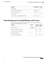
Page 93: ...sceivers Connectors and Cables page 87 3 kW AC Power Cord Specifications page 88 Environmental Specifications Specification Environment 32 to 104 F 0 to 40 C Ambient operating temperature Temperature 50 to 140 F 10 to 60 C Ambient operating temperature when using SFP10G USR transceivers 40 to 158 F 40 to 70 C Ambient nonoperating 5 to 95 Ambient noncondensing Relative humidity 0 to 13 123 feet 0 t...

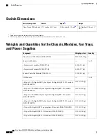
Page 94: ...g Supervisor B module N9K SUP B 2 1 9 lb 0 9 kg System Controller Module N9K SC A 1 to 4 I O Modules 10 8 lb 4 9 kg 48 port 1 10 Gigabit SFP plus 4 port 40 Gigabit QSFP I O module N9K X9464PX 10 0 lb 4 5 kg 48 port 1 10 GBASE T plus 4 port 40 Gigabit QSFP I O module N9K X9464TX 12 6 lb 5 7 kg 48 port 1 10 GBASE T plus 4 port 40 Gigabit QSFP I O module N9K X9564TX 11 5 lb 5 2 kg 48 port 1 10 Gigabi...

Page 95: ... maximum amount of power required for each switch module and fan tray Typically power consumption is less for each module Typical Power Maximum Power Quantity Component 1 or 2 must be same type Supervisor Modules 69 W 80 W Supervisor A module N9K SUP A 75 W 90 W Supervisor B module N9K SUP B 2 System Controller Modules 13 W 25W System Controller N9K SC A Cisco Nexus 9504 NX OS Mode Switch Hardware...

Page 96: ...c Modules N9K C9504 FM 95 W 137 W 3 Fan Tray N9K C9504 FAN Maximum Power Available to the Switch The maximum power available for operations depends on the input power from your power source the number and output capabilities of your power supplies and the power redundancy mode that you use The following table lists the amount of power available for 3 kW power supplies depending on power inputs num...

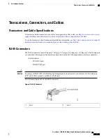
Page 97: ...tml RJ 45 Connectors The RJ 45 connector connects Category 3 Category 5 Category 5e Category 6 or Category 6A foil twisted pair or unshielded twisted pair cable from the external network to the following module interface connectors Switch chassis CONSOLE port MGMT ETH port To comply with GR 1089 intrabuilding lightning immunity requirements you must use a foil twisted pair FTP cable that is proper...

Page 98: ...B AC 16A CH Peoples Republic of China 16A 250 VAC CAB AC 2500W EU Continental Europe 16A 250 VAC CAB AC 2500W INT International 16A 250 VAC CAB AC 2500W ISRL Israel 16A 250 VAC CAB AC 2500W US1 Japan and North America non locking 200 240 VAC operation Cisco Nexus 9504 NX OS Mode Switch Hardware Installation Guide 88 System Specifications 3 kW AC Power Cord Specifications ...

Page 99: ...h America locking 200 240 VAC operation 16A 250 VAC CAB C19 CBN Power distribution unit PDU 16A 250 VAC CAB ACS 16 Switzerland NEMA L5 20 to IEC C19 6 feet 1 8 m CAB L520P C19 US North America Cisco Nexus 9504 NX OS Mode Switch Hardware Installation Guide 89 System Specifications 3 kW AC Power Cord Specifications ...

Page 100: ...Cisco Nexus 9504 NX OS Mode Switch Hardware Installation Guide 90 System Specifications 3 kW AC Power Cord Specifications ...

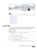
Page 101: ...ower supplies are fully functional or have a fault condition The following table describes what each of these LEDs can indicate Table 4 Chassis LED Descriptions Status Color LED The operator has activated this LED to identify this chassis Flashing blue BCN This chassis is not being identified Off Supervisor modules are all operational Green SUP Check the Supervisor Module LEDs for more information...

Page 102: ...dancy mode differs from the operational power redundancy Amber System Controller LEDs The system controller module LEDs are located on the left side of the module The following table describes the possible states for each of these LEDs Table 5 System Controller LED Descriptions Status Color LED The operator has activated this LED to identify this module in the chassis Flashing blue BCN This module...

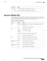
Page 103: ... LED The operator has activated this LED to identify this module in the chassis Flashing blue BCN This module is not being identified Off This module is operational Green STS This module is booting up Flashing amber Temperature exceeds major alarm threshold Flashing red The module is not receiving power Off This module is operational and in active mode Green ACT This module is operational and in s...

Page 104: ... fan tray are operational Green FAB At least one fabric module behind this fan tray is not operating Amber No power is going to the fabric module behind this fan tray Off Fabric Module LEDs The fabric modules are located behind the fan trays Table 8 Fabric Module LED Descriptions Status Color LED The operator has activated this LED to identify this module in the chassis Blue top LED This module is...

Page 105: ...g a reliable connection with the supervisor The module has failed diagnostic tests and has powered down An overtemperature condition has occurred A major temperature threshold has been exceeded during environmental monitoring Flashing red Indicates one of the following The module is booting up or initializing The module is resetting and both ejector levers are out The module has been inserted duri...

Page 106: ...ll of the installed power supplies are not receiving power or an uninstalled power supply is not receiving power Off Off Power supply is operating but a warning condition has occurred possibly one of the following conditions High temperature High power Slow power supply fan Low voltage Power supply is installed in the chassis but was disconnected from the power source Flashing amber Off Power supp...

Page 107: ...the contents for the accessory kit N9K C9504 ACK Quantity Description Illustration 1 kit Rack Mount Kit N9K C9504 RMK 12 24 x 3 4 in Phillips screws 24 M6 x 19 mm Phillips screws 24 Adjustable bottom support rails 2 1 RJ 45 rollover cable 1 DB 9F RJ 45F PC terminal Cisco Nexus 9504 NX OS Mode Switch Hardware Installation Guide 97 ...

Page 108: ... www cisco com warp public 687 Directory DirTAC shtml If you purchased this product through a Cisco reseller you might receive additional contents in your kit such as documentation hardware and power cables Note The product shipment includes a power cord for each 3 kW AC power supply You must supply a 6 AWG cable for up to 45 A The shipped cables depend on your specification when placing an order ...

Page 109: ... A Israel CAB AC 2500W US1 power cord 250 VAC 16A straight blade NEMA 6 CAB AC C6K TWLK power cord 250 VAC 16A twist lock NEMA L6 20 CAB C19 CBN cabinet jumper power cord 250 VAC 16A C20C CAB ACS 16 power cord 16 A Switzerland CAB L520P C19 US NEMA L5 20 to IEC C19 6 ft US Cisco Nexus 9504 NX OS Mode Switch Hardware Installation Guide 99 Accessory Kits Accessory Kit Contents ...
Page 110: ...Cisco Nexus 9504 NX OS Mode Switch Hardware Installation Guide 100 Accessory Kits Accessory Kit Contents ...
Reviews: