background image

6

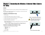
Chapter 3: Getting to Know the Wireless-G Internet Video Camera
Camera LCD Screen and Built-in Microphone

Wireless-G Internet Video Camera

Chapter 3: Getting to Know the Wireless-G Internet Video 
Camera

Camera LCD Screen and Built-in Microphone

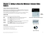
The Camera has a LCD screen that indicates the Camera’s current IP address and whether it is a fixed or dynamic 
address. If the Camera uses a fixed IP address, then the screen will display the word “FIXED.” If the Camera uses 
a dynamic IP address, then the screen will display the word “DHCP.” 

The built-in microphone is located approximately one inch below the LCD screen, in the middle of the Camera’s 
front panel. It has a range of approximately 9 feet (3 meters), depending on environmental conditions.

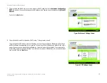
Camera LEDs

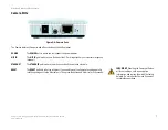
The Camera has four LEDs to let you know how the Camera is functioning.

READY

Green. The 

READY

 LED lights up when the Camera is powered on. It flashes while the 

Camera is initializing and is steadily lit when the Camera is ready for use.

ACT/LINK

Green. The 

ACT/LINK

 LED flashes when there is activity.

ETHERNET

Green. The 

ETHERNET 

LED lights up when there is a connection to a wired network. It flashes 

when data is transmitted to or received from the wired network.

WIRELESS

Green. The 

WIRELESS

 LED lights up when there is a connection to a wireless network. It 

flashes when data is transmitted to or received from the wireless network.

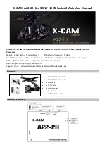
Camera Head

The Camera head and its focus ring allow you to modify the aim and focus of the Camera.

To alter the Camera’s aim, swivel the Camera head.

To adjust the Camera’s focus, rotate the dark gray focus ring.

Figure 3-1: Camera LCD Screen and Built-in Microphone

Figure 3-2: Camera LEDs

Figure 3-3: Camera Head

Built-in 

Microphone

Summary of Contents for Linksys WVC54G

Page 1: ...ADivision of Cisco Systems Inc Model No Internet Video Camera Wireless G WVC54G V1 1 User Guide WIRELESS GHz 2 4802 11g ...

Page 2: ...tems when reading this guide In addition to these symbols there are definitions for technical terms that are presented like this Also each figure diagram screenshot or other image is provided with a figure number and description like this Figure numbers and descriptions can also be found in the List of Figures section in the Table of Contents This exclamation point means there is a Caution or warn...

Page 3: ... Overview 8 Connection to a Wired Network for Setup 8 Connection to a Wireless Ad Hoc Network for Setup 8 Moving the Camera to a Different Network 9 Chapter 5 Setting up and Mounting the Wireless G Internet Video Camera 10 Setup Wizard 10 Placement Options 16 Audio Option 16 Chapter 6 Installing and Using the Wireless G Internet Video Camera Viewer Recorder Utility 17 Overview 17 Installing the Vi...

Page 4: ...A Troubleshooting 56 Common Problems and Solutions 56 Frequently Asked Questions 59 Appendix B Wireless Security 62 Security Precautions 62 Security Threats Facing Wireless Networks 62 Appendix C Upgrading Firmware 64 Appendix D Windows Help 65 Appendix E Glossary 66 Appendix F Specifications 73 Appendix G Warranty Information 75 Appendix H Regulatory Information 76 Appendix I Contact Information ...

Page 5: ... 6 Network Settings Screen 12 Figure 5 7 IP Settings Screen 12 Figure 5 8 Mode Settings Screen 13 Figure 5 9 Wireless Settings Screen 13 Figure 5 10 Security Settings Screen 14 Figure 5 11 Review New Settings Screen 14 Figure 5 12 Confirmation Screen 15 Figure 5 13 Congratulations Screen 15 Figure 5 14 Stand Option 16 Figure 5 15 Camera Desktop Stand 16 Figure 5 16 Wall Mount Option 16 Figure 5 17...

Page 6: ...re 6 18 Files Screen 26 Figure 6 19 Recorded Files Screen 26 Figure 6 20 Window Showing SnapShot Folders 27 Figure 6 21 Preferences Screen 27 Figure 6 22 Recording Schedule Screen 28 Figure 6 23 Add to Recording Schedule Screen 28 Figure 6 24 Stop Scheduled Recording Screen 29 Figure 6 25 View Video Screen 29 Figure 7 1 SoloLink Service 30 Figure 7 2 SoloLink Welcome Screen 30 Figure 7 3 SoloLink ...

Page 7: ...2 Web based Utility Welcome 40 Figure 7 23 Web Utility Login Screen 40 Figure 7 24 SoloLink DDNS Screen 41 Figure 7 25 Find Available Port Screen 41 Figure 8 1 Camera s Default IP Address 42 Figure 8 2 Web based Utility Welcome 42 Figure 8 3 Security Warning Screen 43 Figure 8 4 Web Utility Login Screen 43 Figure 8 5 Basic Screen 44 Figure 8 6 Confirmation Screen 45 Figure 8 7 WEP Key Settings Scr...

Page 8: ...8 16 Device Removal Screen 50 Figure 8 17 Find Available Port Screen 51 Figure 8 18 Status Screen 52 Figure 8 19 Options Screen 53 Figure 8 20 Administrator Help 54 Figure 8 21 Upgrade Firmware Screen 55 Figure C 1 Upgrade Firmware Screen 64 ...

Page 9: ...ou want the video to be visible from outside your home network you can open an appropriate port on the Router and then create password protected accounts to manage access to the Camera or leave it wide open for the world to see The SoloLink DDNS Service trial sign up included lets you access your Camera using an easy to remember name even if your home Internet connection uses a dynamic IP address ...

Page 10: ... the Setup Wizard for setup and configuration of the Camera as well as how to mount the Camera Chapter 6 Installing and Using the Wireless G Internet Video Camera Utility This chapter explains how to install and use the Wireless G Internet Video Camera Utility on your PC so you can view and record video Chapter 7 Setting up the Linksys SoloLink DDNS Service This chapter discusses the advantages of...

Page 11: ...Appendix E Glossary This appendix gives a brief glossary of terms frequently used in networking Appendix F Specifications This appendix provides the technical specifications for the Camera Appendix G Warranty Information This appendix supplies the warranty information for the Camera Appendix H Regulatory Information This appendix supplies the regulatory information regarding the Camera Appendix I ...

Page 12: ... capabilities of an access point Access points transmit data to PCs equipped with wireless network cards which can roam within a certain radial range of the access point Multiple access points can be arranged to work in succession to extend the roaming range and can be set up to communicate with your Ethernet wired hardware as well If the wireless network is relatively small and needs to share res...

Page 13: ...omputers Wireless B and Wireless G PCI Adapters model numbers WMP11 and WMP54G for your desktop PCs and Wireless B and Wireless G USB Adapters model numbers WUSB11 and WUSB54G for your computers when you want to enjoy USB connectivity With these and many other Linksys products your networking options are limitless Go to the Linksys website at www linksys com for more information about products tha...

Page 14: ...e Camera has four LEDs to let you know how the Camera is functioning READY Green The READY LED lights up when the Camera is powered on It flashes while the Camera is initializing and is steadily lit when the Camera is ready for use ACT LINK Green The ACT LINK LED flashes when there is activity ETHERNET Green The ETHERNET LED lights up when there is a connection to a wired network It flashes when d...

Page 15: ...of your external microphone optional ETHERNET The ETHERNET port is where you will connect the Ethernet network cable RESET The RESET button is what you will press if you need to reset the Camera Insert a paper clip into the opening next to the Ethernet port Then press the button and hold it in for five seconds IMPORTANT Resetting the Camera will erase all of your settings such as encryption inform...

Page 16: ... cable to the Ethernet port on the Camera See Figure 4 1 4 Connect the power adapter to the Power port on the Camera 5 Plug the power adapter into an electrical outlet The Camera s Ready LED flashes while the Camera is initializing The Camera is ready for use when the Ready and Ethernet LEDs are solidly lit Proceed to Chapter 5 Setting up and Mounting the Wireless G Internet Video Camera Connectio...

Page 17: ...network follow these instructions 1 Unplug the power adapter from the Camera 2 Unplug the Ethernet network cable from the Camera 3 Re connect the power adapter to the Power port on the Camera The Camera s Ready LED flashes while the Camera is initializing The Camera is ready for use when the Ready and Wireless LEDs are solidly lit Proceed to Chapter 5 Setting up and Mounting the Wireless G Interne...

Page 18: ...your CD ROM drive Setup Click the Setup button to begin the installation process Install Viewer Recorder Utility Click this button to install the Camera s Viewer Recorder Utility on your PC Setup SoloLink DDNS Service Click the Setup SoloLink DDNS Service button to configure and use Linksys s Dynamic Domain Name System DDNS service User Guide Click this button to open the PDF file of this User Gui...

Page 19: ...ers enter admin in the Administrator Name and Administrator Password fields later you can change these through the Web based Utility Then click the OK button 6 On the Basic Settings screen you can alter the following settings Camera Name You can give the Camera a unique name Memorable names are helpful especially if you are using multiple Cameras on the same network It should have 15 characters or...

Page 20: ...ed Automatic Configuration DHCP in step 7 then proceed to step 9 If you selected Static IP Address then the IP Settings screen will appear Enter an IP Address Subnet Mask and Default Gateway appropriate for your network You must specify an IP Address and Subnet Mask on this screen If you are unsure about the Default Gateway it is better to leave this field blank Then complete the Primary DNS and o...

Reviews: