background image

DETAILED STEPS

Step 1

Disconnect the power cord from the power source. Do not touch any metal on the power cord when it is still connected
to the power supply.

Step 2

Loosen the tie and remove the power cord from the tie-and holder.

Step 3

Remove the power cord from the power connection on the power supply. Do not touch the metal prongs embedded in
the power supply.

Step 4

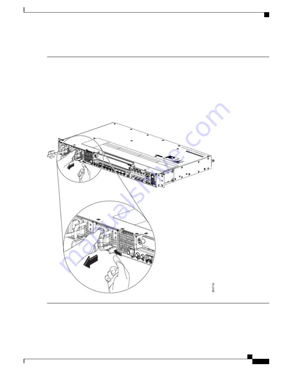
Grasp the power supply handle. Simultaneously press the power supply lock towards the left and pull the power supply
out from the chassis while supporting it with the other hand.

Figure 30: Removing the AC Power Supply Module

Cisco ASR-920-12SZ-IM Aggregation Services Router Hardware Installation Guide    

79

Installing the Cisco ASR 920 Series Router

Removing the AC Power Supply Module

Summary of Contents for ASR-920-12SZ-IM

Page 1: ...es Router Hardware Installation Guide First Published 2016 07 04 Americas Headquarters Cisco Systems Inc 170 West Tasman Drive San Jose CA 95134 1706 USA http www cisco com Tel 408 526 4000 800 553 NETS 6387 Fax 408 527 0883 Text Part Number ...

Page 2: ... Cisco Systems Inc All rights reserved ...

Page 3: ...t Copper Ports 2 GE SFP Ports 2 SFP Ports 3 External Interfaces 8 Network Interfaces 8 Network Timing Interfaces 9 External Alarm Inputs 9 Management Interfaces 9 Management ENET Port 9 RS232 Console Port 9 USB Console 10 USB Mass Storage 10 Zero Touch Provisioning Button 10 RS232 Auxiliary Console Port 10 Power Supply and Fans 10 LED Indicators 11 PWR and STAT LEDs 11 CPU Management Port LEDs 13 ...

Page 4: ...Checklist 23 Site Selection Guidelines 24 Environmental Requirements 24 Physical Characteristics 24 Air Flow Guidelines 24 Air Flow Guidelines for ETSI Rack Installation 26 Floor Loading Considerations 26 Site Power Guidelines 27 Electrical Circuit Requirements 27 Site Cabling Guidelines 27 Asynchronous Terminal Connections 28 Interference Considerations 28 Electromagnetic Interference 28 Radio Fr...

Page 5: ...r in a Rack 45 Installing the Router Chassis in the Rack 46 Attaching the Cable Guides 47 Wall Mounting the Router 49 Attaching the Brackets to the Router for Wall Mounting 49 Mounting Router on the Wall 50 Installing and Removing SFP Modules 52 Installing SFP Modules 52 Removing SFP Modules 54 Connecting to the Copper Ports 55 Connecting to SFP Modules 56 Connecting to Fiber Optic SFP Modules 56 ...

Page 6: ...g to the Console Port Using Mac OS X 81 Connecting to the Console Port Using Linux 82 Installing the Cisco USB Device Driver 82 Uninstalling the Cisco USB Driver 84 Connecting to the EIA Console Port 85 Connecting a Management Ethernet Cable 87 Installing and Removing SFP and SFP Modules 87 Connecting a USB Flash Device 87 Removing a USB Flash Device 88 Connecting Timing Cables 88 Connecting Cable...

Page 7: ...ing Configuration Settings 97 Saving the Running Configuration to NVRAM 97 Safely Powering Off the Router 97 C H A P T E R 5 Troubleshooting 99 Pinouts 99 GPS Port Pinouts 99 Time of Day Port Pinouts 100 Alarm Port Pinouts 100 Management GigabitEthernet Port Pinouts 101 USB Console Port Pinouts 101 USB Flash or MEM Port Pinouts 102 Optical Fiber Specifications 102 Alarm Conditions 102 LED Summary ...

Page 8: ...Cisco ASR 920 12SZ IM Aggregation Services Router Hardware Installation Guide viii Contents ...

Page 9: ... chassis is coated with an acrylic based material to help improve the reliability against air borne contamination Document Revision History The following table lists the major changes made to this document Change Summary Date Release First Release May 29 2015 Cisco IOS XE Release 3 16 S Document Audience This guide is intended for users who are responsible for installing the Cisco ASR 920 Series A...

Page 10: ...nt Conventions This document uses the following conventions Indication Convention Commands and keywords and user entered text appear in bold font bold font Document titles new or emphasized terms and arguments for which you supply values are in italic font italic font Elements in square brackets are optional Required alternative keywords are grouped in braces and separated by vertical bars x y z O...

Page 11: ...y performing the action described in the paragraph Timesaver Means reader be warned In this situation you might perform an action that could result in bodily injury Warning IMPORTANT SAFETY INSTRUCTIONS This warning symbol means danger You are in a situation that could cause bodily injury Before you work on any equipment be aware of the hazards involved with electrical circuitry and be familiar wi...

Page 12: ...ts all new and revised Cisco technical documentation Subscribe to the What s New in Cisco Product Documentation which lists all new and revised Cisco technical documentation as an RSS feed and delivers content directly to your desktop using a reader application The RSS feeds are a free service Cisco ASR 920 12SZ IM Aggregation Services Router Hardware Installation Guide 12 Preface Obtaining Docume...

Page 13: ...R 920 Router Features page 1 GigabitEthernet Copper Ports page 2 GE SFP Ports page 2 SFP Ports page 3 External Interfaces page 8 Cisco ASR 920 Router Features The router provides 1GE 10GE MPLS H QoS high availability hardware design advanced Ethernet Operations Administration and Maintenance OAM as well as advanced timing support including satellite timing GNSS based clocking and PoE in one platfo...

Page 14: ...ed by the 802 3x standard Frame size of 9216 bytes Synchronous ENET operation that provides its recovered receive clock as an input clock source for the SETS as well as uses the system wide reference clock to derive its transmit clock GE SFP Ports The GE SFP ports support the following features 100Base FX and 1000Base X SFP modules Digital optical monitoring as specified by the SFP Any mix of SFPs...

Page 15: ...tical transceiver module Any mix of SFPs is supported unless specifically noted Pause flow control as defined by the 802 3x standard Frame size of 9216 bytes Cisco ASR 920 12SZ IM Aggregation Services Router Hardware Installation Guide 3 Cisco ASR 920 Series Aggregation Services Router Overview SFP Ports ...

Page 16: ...Front Panel of Cisco ASR 920 12SZ IM Router With DC Power Supply Figure 2 Front Panel of Cisco ASR 920 12SZ IM Router With AC Power Supply Cisco ASR 920 12SZ IM Aggregation Services Router Hardware Installation Guide 4 Cisco ASR 920 Series Aggregation Services Router Overview SFP Ports ...

Page 17: ...r 4 USB Memory port 14 SMB Snap in connector 10MHZ 5 USB Console port 15 SMB Snap in connector 1PPS 6 Zero Touch Provisioning button 16 Four 1G 10G SFP 7 RS232 Console port 17 Interface Module 8 RS232 Aux Console port 18 Four 1G SFP 9 Cisco ASR 920 12SZ IM Aggregation Services Router Hardware Installation Guide 5 Cisco ASR 920 Series Aggregation Services Router Overview SFP Ports ...

Page 18: ...h x Depth x Height Total weight 4 83 kg Weight of PSU 0 59 kg Weight of Fan 0 33 kg Weight One RU Rack Unit Front to back Airflow Front cable access Cable access 60 Gbps 95 Mpps System throughput Power Supply Yes Redundant Yes AC 85V AC to 264V AC nominal 100 240 VAC Voltage Range 47 Hz to 63 Hz nominal 50 60 Hz Frequency Range 360 W Maximum Power Yes DC Cisco ASR 920 12SZ IM Aggregation Services ...

Page 19: ...sco ASR920 Data sheet Supported Interface Modules Front or rear rail 19 or 23 inches ETSI 300 mm open cabinet Wall mount Mounting option 12x1G and 4x10G 1G ports Port Configuration 4x10G SFP Port 12 15 4x1G SFP Port 8 11 8x1G PoE RJ45 Cu ports 0 7 Port Numbering Ports 12 to 15 are Dual Rate ports Combo Ports Link Activity Fault Copper 1G 10G Port LEDs Four temperature sensors Temperature Sensors E...

Page 20: ...00 modes GE Copper RJ 45 ports supports 10 100 1000 operation All eight copper RJ 45 ports support PoE PoE UPoE with overall power budget of 180 W PoE is not supported when the system is powered with 24 V DC Note 10GE SFP supports 10G 1G mode depending on the SFP SFP in the network interface slot Cisco ASR 920 12SZ IM Aggregation Services Router Hardware Installation Guide 8 Cisco ASR 920 Series A...

Page 21: ...he front panel Normally Open indicates that no current flows through the alarm circuit and the alarm is generated when the current is flowing Each alarm input can be provisioned as critical major or minor Management Interfaces The following management interfaces are supported Management ENET Port A single management copper ENET port supporting 100 1000Base T operation is provided on the front pane...

Page 22: ...e logs and so on More than 8 GB is not supported in ROMMON mode Note Zero Touch Provisioning Button The Zero Touch Provisioning ZTP button on the front panel initiates the ZTP process on a short press of less than eight seconds Pressing the ZTP button for more than eight seconds causes a board reset RS232 Auxiliary Console Port The RS232 Aux console port provides transmission Tx reception Rx and g...

Page 23: ... operating temperature of 70º C in case of failure of a single fan operating temperature of 65º C The fan tray is field replaceable LED Indicators This section describes the different types of LEDs and their behavior PWR and STAT LEDs The PWR LEDs are available on the front panel These LEDs provide power on the board PWR status During power up state these LEDs provide booting status and report err...

Page 24: ...ashing Amber and Green alternatively Both LEDs turn Green once provisioning is complete ZTP process has begun A short press of the ZTP button triggers the provisioning A longer press of more than eight seconds resets the board Note Flashing Amber Flashing Amber IOS XE image is booting Off Green Successfully booted and system is operating normally Green Green A minor alarm or synchronization is in ...

Page 25: ...in 100 Mbps Amber Activity in 100 Mbps Blinking Amber Link down Off Link up in full duplex Green Right Link up in half duplex Off SFP LEDs Each SFP port has an LED indicator Table 5 SFP Port LED Indication Indication LED State LED Link up in 1000Base X 100Base FX Green Labeled same as the SFP port number Activity in 1000 Base X 100Base FX Blinking Green Fault Error Link down Amber Administratively...

Page 26: ... Table 7 RJ 45 LED Indication Indication LED State Link up in 10 100 1000Base T Green Activity in 10 100 1000Base T Blinking Green Fault Error Link down Amber Administratively down Off Power Supply Unit LEDs Each power supply unit has a corresponding LED on the front panel Table 8 PSU LED Indication Power Supply Condition FAIL LED Power LED Power Supply ON valid input output Off Green PSU Warning ...

Page 27: ...ort LEDs Link Event Off Off ROMMON Off Off IOS Shut Amber Amber IOS No shut cable disconnect Green Green IOS No shut Link Up Table 10 Dual Rate Port LED Indication Dual Rate 1G 10G Port LEDs Event Off ROMMON Off IOS Shut Amber IOS No shut cable disconnect Green IOS No shut Link Up Table 11 Management Port LED Indication Management Port LEDs Link Duplex Event Green Off ROMMON Off Off IOS Shut Cisco...

Page 28: ... is removed or replaced there is no need to power down the router However when the fan tray is removed from the router the router shuts down automatically after some time depending on the ambient temperature The time duration before the router shuts down is shown in the table below Licensing The router supports the following types of licenses Port Licensing Port Upgrade license is available as a P...

Page 29: ...r device certificate WDC is stored in the system Note Cisco Smart Licensing Smart Licensing is usage based licensing where devices register with the Cisco Secure server Cisco ASR 920 12SZ IM Aggregation Services Router Hardware Installation Guide 17 Cisco ASR 920 Series Aggregation Services Router Overview Licensing ...

Page 30: ...Cisco ASR 920 12SZ IM Aggregation Services Router Hardware Installation Guide 18 Cisco ASR 920 Series Aggregation Services Router Overview Licensing ...

Page 31: ...siderations page 22 Preventing ESD Damage page 22 Site Planning page 23 Air Flow Guidelines page 24 Floor Loading Considerations page 26 Site Power Guidelines page 27 Electrical Circuit Requirements page 27 Site Cabling Guidelines page 27 Asynchronous Terminal Connections page 28 Interference Considerations page 28 Installation Checklist page 31 Creating a Site Log page 32 Chassis Lifting Guidelin...

Page 32: ...necklaces and watches Metal objects will heat up when connected to power and ground and can cause serious burns or weld the metal object to the terminals Statement 43 Warning For other standard warning messages and their translations see the Regulatory Compliance and Safety Information for the Cisco ASR 920 Series Aggregation Services Router document SafetyGuidelinesforPersonalSafetyandEquipmentPr...

Page 33: ...ing a router chassis or network processor module Performing most hardware upgrades Never install equipment that appears damaged Carefully examine your work area for possible hazards such as moist floors ungrounded power extension cables and missing safety grounds Never assume that power is disconnected from a circuit always check Never perform any action that creates a potential hazard to people o...

Page 34: ... and cord must operate effectively If no wrist strap is available ground yourself by touching a metal part of the chassis When installing a component use any available ejector levers or captive installation screws to properly seat the bus connectors in the backplane or midplane These devices prevent accidental removal provide proper grounding for the system and help to ensure that bus connectors a...

Page 35: ... wiring rules If you turn off your system wait at least 30 seconds before turning it on again to avoid damage of system components Site Planning Checklist Use the following checklist to perform and account for all the site planning tasks described in this chapter The site meets the environmental requirements The site s air conditioning system can compensate for the heat dissipation The floor space...

Page 36: ...inst airborne contaminants dust moisture insects pests corrosive gases polluted air or other reactive elements present in the outside air To achieve this level of protection we recommend that the unit be installed in a fully sealed enclosure or cabinet Examples of such cabinets include IP65 cabinets with heat exchanger complying with Telecordia GR487 Temperature must be maintained within 40º C to ...

Page 37: ...flow through the equipment rack it is recommended that you maintain a minimum clearance distance as mentioned below at all times front clearance 12 7 cm rear clearance 14 cm Note the following points Cisco ASR 920 12SZ IM Aggregation Services Router Hardware Installation Guide 25 Preparing for Installation Air Flow Guidelines ...

Page 38: ...cks to give the router maximum cooling air and clean power Avoid installing the router in a location in which the chassis air intake vents may draw in the exhaust air from adjacent equipment Consider how the air flows through the router the airflow direction is front to back with ambient air drawn in from the vents located on the sides of the chassis Air Flow Guidelines for ETSI Rack Installation ...

Page 39: ...ided as part of the building installation Install only in accordance with national and local wiring regulations Caution The router installation must comply with all the applicable codes and is approved for use with copper conductors only The ground bond fastening hardware should be of compatible material and preclude loosening deterioration and electrochemical corrosion of hardware and joined mate...

Page 40: ...elded conductors to destroy electronic devices If you have had problems of this sort in the past you may want to consult experts in electrical surge suppression and shielding Asynchronous Terminal Connections The router provides a console port to connect a terminal or computer for local console access The port has an RJ 45 connector and supports RS 232 asynchronous data with distance recommendatio...

Page 41: ...ldings you should consider the effect that a lightning strike in your vicinity might have on the router The electromagnetic pulse EMP generated by lightning or other high energy phenomena can couple enough energy into unshielded conductors to damage or destroy electronic equipment If you have previously experienced such problems you should consult with RFI and EMI experts to ensure that you have a...

Page 42: ...ng Leveling feet for stability The router is not recommended to be installed in an enclosed rack because the chassis requires an unobstructed flow of cooling air to maintain acceptable operating temperatures for its internal components If you use an enclosed rack ensure that the air flow requirements are maintained as discussed in Air Flow Guidelines Caution Equipment Rack Guidelines The placement...

Page 43: ...hat collect dust Follow ESD prevention procedures to avoid damage to equipment Damage from static discharge can cause immediate or intermittent equipment failure Locating for Proper Airflow Ensure that the router location has enough airflow to keep the system operating within the environmental characteristics and the air temperature is sufficient to compensate for the heat dissipated by the system...

Page 44: ...to AC sources and router DC power cables connected to DC sources and router Network interface cables and devices connected System power turned on System boot complete STATUS LED is on Correct software configuration displayed after system banner appears Creating a Site Log The Site Log provides a record of all the actions related to installing and maintaining the router Keep it in an accessible pla...

Page 45: ...attempt to lift or tilt the chassis using the handles on modules such as power supplies fans or cards these types of handles are not designed to support the weight of the unit Lift the unit only by using handles that are an integral part of the chassis or by grasping the chassis underneath its lower edge Statement 163 Warning Tools and Equipment You need the following tools and equipment to instal...

Page 46: ... shipping container You will need the container if you move or ship the Cisco ASR 920 24SZ IM ASR 920 24SZ M ASR 920 24TZ M Router in the future DETAILED STEPS Step 1 Inspect the box for any shipping damage If there is obvious physical damage contact your Cisco service representative Step 2 Unpack the Cisco ASR 920 24SZ IM ASR 920 24SZ M ASR 920 24TZ M Router Step 3 Perform a visual inspection of ...

Page 47: ...and DC power supplies are provided as ordered Note Power cord if an AC power supply was shipped There are no cords for the DC power supply units If you do not specify the type of power cable US power cable for the AC router variant is supplied Note Optional equipment Most Cisco documentation is available online The Cisco ASR 920 Series Aggregation Services Router Pointer Card that is shipped with ...

Page 48: ...Cisco ASR 920 12SZ IM Aggregation Services Router Hardware Installation Guide 36 Preparing for Installation Unpacking and Verifying the Shipped Contents ...

Page 49: ...llation page 3 24 Installing the Power Supply page 3 25 Connecting the Router to the Network page 3 35 Prerequisites page 38 Installing the Router in a Rack page 38 Mounting the Router in a Rack page 45 Installing the Router Chassis in the Rack page 46 Attaching the Cable Guides page 47 Wall Mounting the Router page 49 Installing and Removing SFP Modules page 52 Connecting to the Copper Ports page...

Page 50: ...r in the equipment rack This arrangement provides extra space in front of the router for the cables and allows you to close the doors of racks equipped with front close doors To attach or replace the rack mounting brackets see the Attaching Brackets to the Router section The rack mounting brackets are slotted to allow the router to be mounted in racks with EIA 1 25 inch 3 175 cm or WECO 1 0 inch 2...

Page 51: ...g Brackets for 19 Inch Racks section For 23 inch racks use part number 700 40065 01 see Attaching Brackets for 23 Inch Racks section For ETSI racks use part number 700 40067 01 see Attaching Brackets for ETSI Racks section The bracket mounting screws are pre installed on the router Depending on the bracket mounting position of the chassis you must remove the appropriate screws fix the bracket and ...

Page 52: ...ows how to attach brackets for 19 inch racks on the router Figure 7 Attaching Brackets for 19 Inch Racks Cisco ASR 920 12SZ IM Aggregation Services Router Hardware Installation Guide 40 Installing the Cisco ASR 920 Series Router Attaching Brackets to the Router ...

Page 53: ...llips flat head screws 1 Rear mounting position 4 Mid mounting position 3 Cisco ASR 920 12SZ IM Aggregation Services Router Hardware Installation Guide 41 Installing the Cisco ASR 920 Series Router Attaching Brackets to the Router ...

Page 54: ...ows how to attach brackets for 23 inch racks on the router Figure 8 Attaching Brackets for 23 Inch Racks Cisco ASR 920 12SZ IM Aggregation Services Router Hardware Installation Guide 42 Installing the Cisco ASR 920 Series Router Attaching Brackets to the Router ...

Page 55: ...llips flat head screws 1 Rear mounting position 4 Mid mounting position 3 Cisco ASR 920 12SZ IM Aggregation Services Router Hardware Installation Guide 43 Installing the Cisco ASR 920 Series Router Attaching Brackets to the Router ...

Page 56: ...shows how to attach brackets for ETSI racks on the router Figure 9 Attaching Brackets for ETSI Racks Cisco ASR 920 12SZ IM Aggregation Services Router Hardware Installation Guide 44 Installing the Cisco ASR 920 Series Router Attaching Brackets to the Router ...

Page 57: ... figure shows the types of mounting brackets 4 Determine the mounting position Front Mid or Rear mounting of the router For 19 inch racks see Attaching Brackets for 19 Inch Racks section For 23 inch racks see Attaching Brackets for 23 Inch Racks section For ETSI racks see Attaching Brackets for ETSI Racks section 5 Locate the mounting holes of the router 6 Align the rack mounting bracket with the ...

Page 58: ...e rack and secure with four 6 32 x 0 25 inch mounting screws two on each side Step 9 Tighten the screws using a 1 4 inch flat blade screwdriver each side The recommended maximum torque is 10 in lb Installing the Router Chassis in the Rack Ensure adequate air flow when mounting the router in a rack For more information see the Air Flow Guidelines section Note Install the cable guides before install...

Page 59: ...rough the holes in the bracket and into the threaded holes in the equipment rack posts Step 4 Use a tape measure and level to verify that the chassis is installed straight and level Attaching the Cable Guides The Cisco ASR 920 Series Router supports the following cable guides A920 CBL GUIDE left and right help in routing the cables from all components on the front panel thereby enabling a proper c...

Page 60: ... maximum torque is 3N m DETAILED STEPS Step 1 Position the cable guide left and cable guide right against the front of the chassis and align the four screw holes as shown in the following figure Figure 11 Cable Guide Installation For 19 inch Rack Brackets Figure 12 Cable Guide Installation For ETSI Rack Brackets Cisco ASR 920 12SZ IM Aggregation Services Router Hardware Installation Guide 48 Insta...

Page 61: ...ounting the Router To install the router on a wall follow the instructions in these procedures Attaching the Brackets to the Router for Wall Mounting While wall mounting the router always ensure that the power supplies are at the top position Note Cisco ASR 920 12SZ IM Aggregation Services Router Hardware Installation Guide 49 Installing the Cisco ASR 920 Series Router Wall Mounting the Router ...

Page 62: ...outer on the Wall For the best support of the router and cables ensure the router is attached securely to wall studs or to a firmly attached plywood mounting backboard Suitable for mounting on and over a concrete or other non combustible surface only Statement 345 Warning Cisco ASR 920 12SZ IM Aggregation Services Router Hardware Installation Guide 50 Installing the Cisco ASR 920 Series Router Mou...

Page 63: ...e 15 Mounting the Router on the Wall When mounting the router vertically ensure that the power supplies are at the top Caution Cisco ASR 920 12SZ IM Aggregation Services Router Hardware Installation Guide 51 Installing the Cisco ASR 920 Series Router Mounting Router on the Wall ...

Page 64: ...nd that you do not install or remove fiber optic SFP modules with cables attached because of the potential damage to the cables the cable connector or the optical interfaces in the SFP module Disconnect all cables before removing or installing an SFP module Removing and installing an SFP module can shorten its useful life Do not remove and insert SFP modules more often than is absolutely necessary...

Page 65: ...n the rear of the slot Figure 17 Installing an SFP Module into an SFP Module Slot Do not remove the dust plugs from the fiber optic SFP module port or the rubber caps from the fiber optic cable until you are ready to connect the cable The plugs and caps protect the SFP module ports and cables from contamination and ambient light Store the dust plugs for later use Caution Step 5 Insert the cable co...

Page 66: ...sert a dust plug into the optical ports of the SFP module to keep the optical interfaces clean 6 Place the removed SFP module in an antistatic bag or other protective environment DETAILED STEPS Step 1 Attach an ESD preventive wrist strap to your wrist and to a bare metal surface on the chassis Step 2 Disconnect the cable from the SFP module and insert a dust plug into the cable end For reattachmen...

Page 67: ...o keep the optical interfaces clean Step 6 Place the removed SFP module in an antistatic bag or other protective environment Connecting to the Copper Ports Copper ports 0 7 are capable of working 10 100 1000 Mbps The router copper ports configure themselves to operate at the speed of attached devices If the attached ports do not support autonegotiation you can explicitly set the speed and duplex p...

Page 68: ...es the interfaces accordingly Therefore you can use either a crossover or a straight through cable for connections to a copper 100 1000 or an SFP module port on the router regardless of the type of device on the other end of the connection Note Step 2 Connect the other end of the cable to an RJ 45 connector on the other device The port LED turns on when both the router and the connected device hav...

Page 69: ... Step 2 Insert one end of the fiber optic cable into the SFP module port Step 3 Insert the other cable end into a fiber optic connector on a target device Step 4 Observe the port status LED The LED turns green when the router and the target device have an established link If the LED is off the target device might not be turned on there might be a cable problem or there might be problem with the ad...

Page 70: ...ct the power at the circuit breaker Otherwise severe injury to you or damage to the router may occur Caution Electric Shock Hazard This fan tray has to be serviced by trained personnel only Caution This equipment must be grounded Never defeat the ground conductor or operate the equipment in the absence of a suitably installed ground conductor Contact the appropriate electrical inspection authority...

Page 71: ...er the exposed area of the ground wire 3 Using a crimping tool as specified by the ground lug manufacturer crimp the ground lug to the ground wire as shown in the following figure 4 Use a Phillips head screwdriver to attach the 2 hole ground lug and wire assembly to the router with the 2 pan head Phillips head screws 5 Connect the other end of the ground wire to a suitable grounding point at your ...

Page 72: ...the other end of the ground wire to a suitable grounding point at your site Installing and Removing the Fan Tray This section describes how to install and remove fan trays Installing the Fan Tray Follow these steps to install the fan tray in the chassis Electric Shock Hazard This fan tray has to be serviced by trained personnel only Caution Always wear the ESD wrist strap when installing or uninst...

Page 73: ...LED STEPS Step 1 Orient the fan tray so that the captive screws are aligned to the chassis cavity on the back panel See the following figure Figure 22 Installing the Fan Tray in the Chassis Step 2 Push the fan assembly into the chassis until the power connector seats in the backplane and the captive installation screws make contact with the chassis Step 3 Tighten the captive installation screws us...

Page 74: ...n assembly in the chassis The fan tray is located to the left of the chassis on the rear side See the following figure 2 Loosen the two fan tray captive installation screws by turning them counterclockwise using a flat blade or number 2 Phillips head screwdriver 3 Grasp the fan assembly with both hands and pull it outward rock it gently if necessary to unseat the fan assembly power connector from ...

Page 75: ...Phillips head screwdriver Step 3 Grasp the fan assembly with both hands and pull it outward rock it gently if necessary to unseat the fan assembly power connector from the backplane Step 4 Pull the fan assembly clear of the chassis and set it aside Interface Module Installation The following sections describe the various tasks of associated with interface module installation Cisco ASR 920 12SZ IM ...

Page 76: ... sides of the interface module The recommended maximum torque is 5 5 in lb 62 N m Step 4 Connect all the cables to each interface module Removing an Interface Module SUMMARY STEPS 1 To remove an interface module disconnect all the cables from the interface module 2 Loosen the locking thumbscrews on both sides of the interface module 3 Slide the interface module out of the router slot by pulling on...

Page 77: ... connection are required to have an external surge protective device SPD provided as part of the building installation to comply with the Telcordia GR 1089 NEBS standard for electromagnetic compatibility and safety Note Do not use interface module and power supply ejector handles to lift the chassis using the handles to lift the chassis can deform or damage the handles Caution Power Connection Gui...

Page 78: ...at the power source side and chassis should protected by a dedicated two pole circuit breaker Guidelines for AC Powered Systems Basic guidelines for AC powered systems include the following Each chassis power supply should have its own dedicated branch circuit The circuit breaker should be sized according to the power supply input rating and local or national code requirements The AC power recepta...

Page 79: ... system earth ground connection has been made See the following figure 2 If necessary remove the blank power supply filler plate from the chassis power supply bay opening by loosening the captive installation screws 3 Verify that power to the DC circuit connected to the power supply you are installing is off To ensure that power has been removed from the DC circuits locate the circuit breakers for...

Page 80: ...C circuits switch the circuit breakers to the OFF position and tape the circuit breaker switches in the OFF position Step 4 Grasp the power supply handle with one hand Place your other hand underneath the power supply Slide the power supply into the power supply bay Make sure that the power supply is fully seated in the bay Step 5 Tighten the captive installation screws of the power supply The rec...

Page 81: ...ndle to the On position Step 2 Verify power supply operation by checking if the respective power supply front panel LED PS0 or PS1 is green Step 3 If the LEDs indicate a power problem see Troubleshooting Step 4 If you are connecting a redundant DC power supply repeat these steps for the second power source If you are connecting a redundant DC power supply ensure that each power supply is connected...

Page 82: ...lies SUMMARY STEPS 1 Locate the terminal block plug 2 Insert the DC input power source wires into the terminal block plug 3 Attach the DC supply wires using the designated screws 4 Use a ratcheting torque screwdriver to torque the terminal block plug captive screw See the following figure Cisco ASR 920 12SZ IM Aggregation Services Router Hardware Installation Guide 70 Installing the Cisco ASR 920 ...

Page 83: ...screw See the following figure Figure 26 Attaching the DC Power Supply Wires Removing the DC Power Supply Module This section provides information about removing and replacing the DC power supply Before performing any of the following procedures ensure that power is removed from the DC circuit Statement 1003 Warning Cisco ASR 920 12SZ IM Aggregation Services Router Hardware Installation Guide 71 I...

Page 84: ...t was included in the accessory kit 3 Switch the power supply circuit breaker switch to the Off O position 4 Pull the terminal block plug connector out of the terminal block head in the power supply See the following figure 5 Loosen the captive screws on the DC power supply 6 Grasp the power supply handle Simultaneously press the power supply lock towards the left and pull the power supply out fro...

Page 85: ... terminal block head in the power supply See the following figure Step 5 Loosen the captive screws on the DC power supply Step 6 Grasp the power supply handle Simultaneously press the power supply lock towards the left and pull the power supply out from the chassis while supporting it with the other hand Figure 27 Removing the DC Power Supply Module Installing the AC Power Supply Module Follow the...

Page 86: ...derneath the power supply Slide the power supply into the power supply bay Make sure that the power supply is fully seated in the bay See the following figure 4 Slide the AC power supply cord inside the tie of the tie and holder and tighten the tie around the power supply cord 5 Plug the power supply cord into the AC power supply Cisco ASR 920 12SZ IM Aggregation Services Router Hardware Installat...

Page 87: ...pply Slide the power supply into the power supply bay Make sure that the power supply is fully seated in the bay See the following figure Figure 28 Installing the AC Power Supply Module Step 4 Slide the AC power supply cord inside the tie of the tie and holder and tighten the tie around the power supply cord Step 5 Plug the power supply cord into the AC power supply Cisco ASR 920 12SZ IM Aggregati...

Page 88: ...s shown in 2 in the figure below DETAILED STEPS Step 1 Plug the power supply cord in the power supply module Step 2 Insert the power supply cord into the tie 1 and tighten the tie around the power supply cord as shown in 2 in the figure below Figure 29 Attaching the AC Power Tie and Clip Cord Cisco ASR 920 12SZ IM Aggregation Services Router Hardware Installation Guide 76 Installing the Cisco ASR ...

Page 89: ...oblem see Troubleshooting for troubleshooting information Step 5 If you are connecting a redundant AC power supply repeat these steps for the second power source If you are connecting a redundant AC power supply ensure that each power supply is connected to a separate power source in order to prevent power loss in the event of a power failure Note Removing the AC Power Supply Module This section d...

Page 90: ... from the power connection on the power supply Do not touch the metal prongs embedded in the power supply 4 Grasp the power supply handle Simultaneously press the power supply lock towards the left and pull the power supply out from the chassis while supporting it with the other hand Cisco ASR 920 12SZ IM Aggregation Services Router Hardware Installation Guide 78 Installing the Cisco ASR 920 Serie...

Page 91: ...nnection on the power supply Do not touch the metal prongs embedded in the power supply Step 4 Grasp the power supply handle Simultaneously press the power supply lock towards the left and pull the power supply out from the chassis while supporting it with the other hand Figure 30 Removing the AC Power Supply Module Cisco ASR 920 12SZ IM Aggregation Services Router Hardware Installation Guide 79 I...

Page 92: ... more information see the Installing the Cisco USB Device Driver section Note SUMMARY STEPS 1 Connect a USB Type A to Type A cable to the USB console port If you are using the USB serial port for the first time on a Windows based PC install the USB driver now according to the instructions in the following sections 2 Connect the USB Type A cable to the PC 3 To communicate with the router start a te...

Page 93: ...B port number 4 Connect to the USB port with the following command followed by the router USB port speed DETAILED STEPS Step 1 Use the Finder to choose Applications Utilities Terminal Step 2 Connect the OS X USB port to the router Step 3 Enter the following commands to find the OS X USB port number Example macbook user cd dev macbook user ls ltr dev usb crw rw rw 1 root wheel 9 66 Apr 1 16 46 tty ...

Page 94: ...e root usb suse dev screen dev ttyACM0 9600 To disconnect the Linux USB console from the terminal window enter Ctrl a followed by then quit Installing the Cisco USB Device Driver A USB device driver must be installed the first time a Microsoft Windows based PC is connected to the USB serial port on the router This procedure describes how to install the Microsoft Windows USB device driver in Micros...

Page 95: ...zip the file asr 9xx_usbconsole_drivers zip Step 2 Double click xrusbser_ver2100_installer exe in the XR21x141x Win DriversOnly Vers2 1 0 0 EXE folder Installation Wizard GUI is displayed Step 3 Click Next The InstallShield Wizard Completed window is displayed Step 4 Click Finish Step 5 Connect the USB cable to the PC and router USB console ports Follow the on screen instructions to complete the i...

Page 96: ...ista Windows 2000 Windows 7 and Windows 8 Disconnect the router console terminal before uninstalling the driver Note SUMMARY STEPS 1 Choose Start Control Panel Add or Remove Programs 2 Scroll to Windows Driver Package Exar corporation xrusbser Ports and click Remove The Program Maintenance window is displayed 3 Click Yes to uninstall the driver Cisco ASR 920 12SZ IM Aggregation Services Router Har...

Page 97: ...rately Note To connect a terminal to the EIA Console port on the router follow these steps SUMMARY STEPS 1 Connect the USB end of the USB to RJ 45 cable to the EIA Console port 2 Connect the RJ 45 end of the DB 9 adapter cable to the USB to RJ 45 cable as shown in the following figure 3 Connect the DB 9 end of the console cable to the DB 9 end of the terminal 4 To communicate with the router start...

Page 98: ...sole port 1 Desktop or system 4 USB to RJ45 adapter 2 Step 3 Connect the DB 9 end of the console cable to the DB 9 end of the terminal Step 4 To communicate with the router start a terminal emulator application such as Microsoft Windows HyperTerminal This software should be configured with the following parameters 9600 baud 8 data bits no parity 1 stop bit no flow control Cisco ASR 920 12SZ IM Agg...

Page 99: ...osed OSP cabling The addition of Primary Protectors is not sufficient protection in order to connect these interfaces metallically to OSP wiring Caution Installing and Removing SFP and SFP Modules The Cisco ASR 920 Series Router supports a variety of SFP and SFP modules including optical and Ethernet modules For information on how to install and remove SFP and SFP modules see the documentation for...

Page 100: ...e memory stick from the USB port Step 2 To replace the Cisco USB Flash memory stick simply insert the module into the USB port labeled USB MEM The Flash memory module can be inserted only one way and can be inserted or removed regardless of whether the router is powered up or not This completes the USB Flash memory installation procedure Connecting Timing Cables The section describes how to connec...

Page 101: ...lded mini coax cable to the Slave unit 2 Connect the other end of the shielded mini coax cable to the 10 Mhz or 1 PPS port on the Cisco ASR 920 Series Router DETAILED STEPS Step 1 Connect one end of a shielded mini coax cable to the Slave unit Step 2 Connect the other end of the shielded mini coax cable to the 10 Mhz or 1 PPS port on the Cisco ASR 920 Series Router Connecting a Cable to the ToD In...

Page 102: ... from the exposed OSP cabling The addition of Primary Protectors is not sufficient protection in order to connect these interfaces metallically to OSP wiring Warning For more information about GPS port pinouts see Troubleshooting section Note Connecting a Cable to the GNSS Antenna Interface SUMMARY STEPS 1 Connect one end of a shielded coaxial cable to the GNSS RF IN port 2 Connect the other end o...

Page 103: ...equire isolation from the exposed OSP cabling The addition of Primary Protectors is not sufficient protection in order to connect these interfaces metallically to OSP wiring Warning Follow these steps to connect a cable to a copper Gigabit Ethernet port SUMMARY STEPS 1 Confirm that the router is powered off 2 Connect one end of the cable to the Gigabit Ethernet port on the router 3 Connect the oth...

Page 104: ...Cisco ASR 920 12SZ IM Aggregation Services Router Hardware Installation Guide 92 Installing the Cisco ASR 920 Series Router Connector and Cable Specifications ...

Page 105: ...tup page 95 Safely Powering Off the Router page 97 Checking Conditions Prior to System Startup Ensure that the following conditions are addressed before starting up the router The optional Gigabit Ethernet Management port cable is installed The chassis is securely mounted and grounded The power and interface cables are connected Your PC with terminal emulation program HyperTerminal or equivalent i...

Page 106: ...Ds The front panel indicator LEDs provide power activity and status information useful during bootup For more detailed information about the LEDs see the LED Indicators section Verifying the Hardware Configuration To display and verify the hardware features enter the following commands show version Displays the system hardware version the installed software version the names and sources of configu...

Page 107: ...e that is available on the router For information on modifying the configuration after you create it see the Cisco IOS configuration and Cisco IOS Master Command List All Releases guides To configure a Cisco ASR 920 Series Router from the console you must connect a terminal or terminal server to the console port on the Cisco ASR 920 Series Router To configure the router using the management Ethern...

Page 108: ...o exit the console session enter the quit command as shown in the following example Example Router quit Configuring Global Parameters When you first start the setup program configure the global parameters These parameters are used for controlling system wide settings Perform the following steps to enter the global parameters SUMMARY STEPS 1 Connect a console terminal to the console port and then b...

Page 109: ...he value of the settings you have entered enter the show running config command at the Router prompt Router show running config To review the changes you have made to the configuration use the show startup config command in the user EXEC mode to see the changes and copy run start stored in the NVRAM Saving the Running Configuration to NVRAM To store the configuration or changes to your startup con...

Page 110: ...er confirming the reload command wait until the system bootstrap message is displayed before powering off the system Example System Bootstrap Version 15 4 3 S1 RELEASE SOFTWARE fc1 Technical Support http www cisco com techsupport Copyright c 2012 by cisco Systems Inc Current image running Boot ROM0 Last reset cause RSP Board UEA platform with 2097152 Kbytes of main memory Step 5 Remove power cable...

Page 111: ...arizes the GPS port pinouts Table 14 GPS Port Pinouts 1PPS input and output 10Mhz input and output Input Pulse Output Pulse Input Sine wave Output Square wave Waveform Input 2 4 volts TTL compatible Output 2 4 volts TTL compatible Input 1 7 volt p p 8 to 10 dBm Output 2 4 volts TTL compatible Amplitude 50 ohms 50 ohms Impedance 26 microseconds 50 percent duty cycle Pulse Width 40 nanoseconds Input...

Page 112: ...4 GND 5 1PPS RS422 signal Input 1PPS_P 6 Time of Day character Output or Input TOD_N 7 Time of Day character Output or Input TOD_P 8 Alarm Port Pinouts The table below summarizes the external alarm input pinouts Table 16 External Alarm Input Pinouts Description Signal Name Pin Alarm input 0 ALARM0_IN 1 Alarm input 1 ALARM1_IN 2 No connect 3 Alarm input 2 ALARM2_IN 4 Alarm input 3 ALARM3_IN 5 No co...

Page 113: ...nal Name Pin TRP0 1 TRP0 2 TRP1 3 TRP2 4 TRP2 5 TRP1 6 TRP3 7 TRP3 8 USB Console Port Pinouts The table below summarizes the USB console port pinouts Table 18 Single USB Console Port Pinouts Description Signal Name Pin 5VDC Vcc 1 Data D 2 Data D 3 Ground Gnd 4 Cisco ASR 920 12SZ IM Aggregation Services Router Hardware Installation Guide 101 Troubleshooting Management GigabitEthernet Port Pinouts ...

Page 114: ...cification for optical fiber transmission defines two types of fiber single mode and multimode Within the single mode category three transmission types are defined short reach intermediate reach and long reach Within the multimode category only short reach is available For information about optical SFP modules see the documentation for the SFP module at http www cisco com en US partner products hw...

Page 115: ...ply LEDs for both the AC and DC power supplies Table 21 PSU LED Indication Power Supply Condition FAIL LED Power LED Power Supply ON valid input output Off Green PSU Warning due to OCP OTP UV OV OP abnormal fan operation PSU continues to operate Red 1Hz blinking Yellow 1Hz blinking PSU failure due to OCP OTP UV OV OP abnormal fan operation No valid output On Off Valid power present shutdown by sys...

Page 116: ...n Tray LEDs Description Color State System is not powered on Off All the fans are working normally Green Single or multiple fan failures and critical error Red Cisco ASR 920 12SZ IM Aggregation Services Router Hardware Installation Guide 104 Troubleshooting Fan Tray LEDs ...

Page 117: ...s as you complete each task Upgrade removal and maintenance procedures Use the Site Log as a record of ongoing router maintenance and expansion history Each time a task is performed on the Cisco ASR 920 Series Router update the Site Log to reflect the following Removal or replacement of interface modules Configuration changes Maintenance schedules and requirements Maintenance procedures performed ...

Page 118: ...Initials Description of Action Performed or Symptom Observed Date Cisco ASR 920 12SZ IM Aggregation Services Router Hardware Installation Guide 106 Site Log ...

Reviews: