


-5
Cisco AS5350 and Cisco AS5400 Universal Gateway Software Configuration Guide
OL-3418-02 B0
Appendix
Getting Started
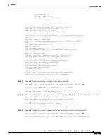
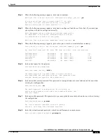
There are 10 controllers on this access server. If you want to use
the full capacity of the access server configure all controllers.
Controller CT3 0,1...etc in software corresponds to Port 0,1...etc
on the back of the access server.
PRI configuration can be configured to controllers all at once
based on your PRI controllers selection. Whereas CAS configuration
will be configured individually for each controller.
Step 13
Enter the number of controllers you will be using for the PRI configuration or press Enter to configure
all controllers.
Enter # of controllers, you will be using for PRI configuration [28]:
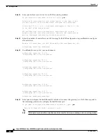
Configuring controller parameters:
Step 14
Press Enter for every slot, port, and channel.
Configuring controller t1 3/0:1
Configuring PRI on this controller.
.
.
.
.
Configuring controller t1 3/0:28
Step 15
Enter yes to use robbed bit signaling on the controller.
Will you be using CT1 (robbed-bit signaling) on this controller? [yes]: yes
Step 16
Enter your telco framing type.
The following framing types are available: esf | sf
Enter the framing type [esf]:
Step 17
Enter your telco line code type.
The following linecode types are available: ami | b8zs
Enter the line code type [b8zs]:
Step 18
Enter the letter corresponding to the signaling type to support modem pooling over the T1 lines or press
Enter to accept the default.
The following line signaling types are available
[a] e&m-fgb
[b] e&m-fgd
[c] e&m-immediate-start
[d] fgd-eana
[e] fgd-os
[f] fxs-ground-start
[g] fxs-loop-start
[h] none
[i] r1-itu
[j] r1-modified
[k] r1-turkey
[l] sas-ground-start
[m] sas-loop-start


