background image

33


Checking the LEDs

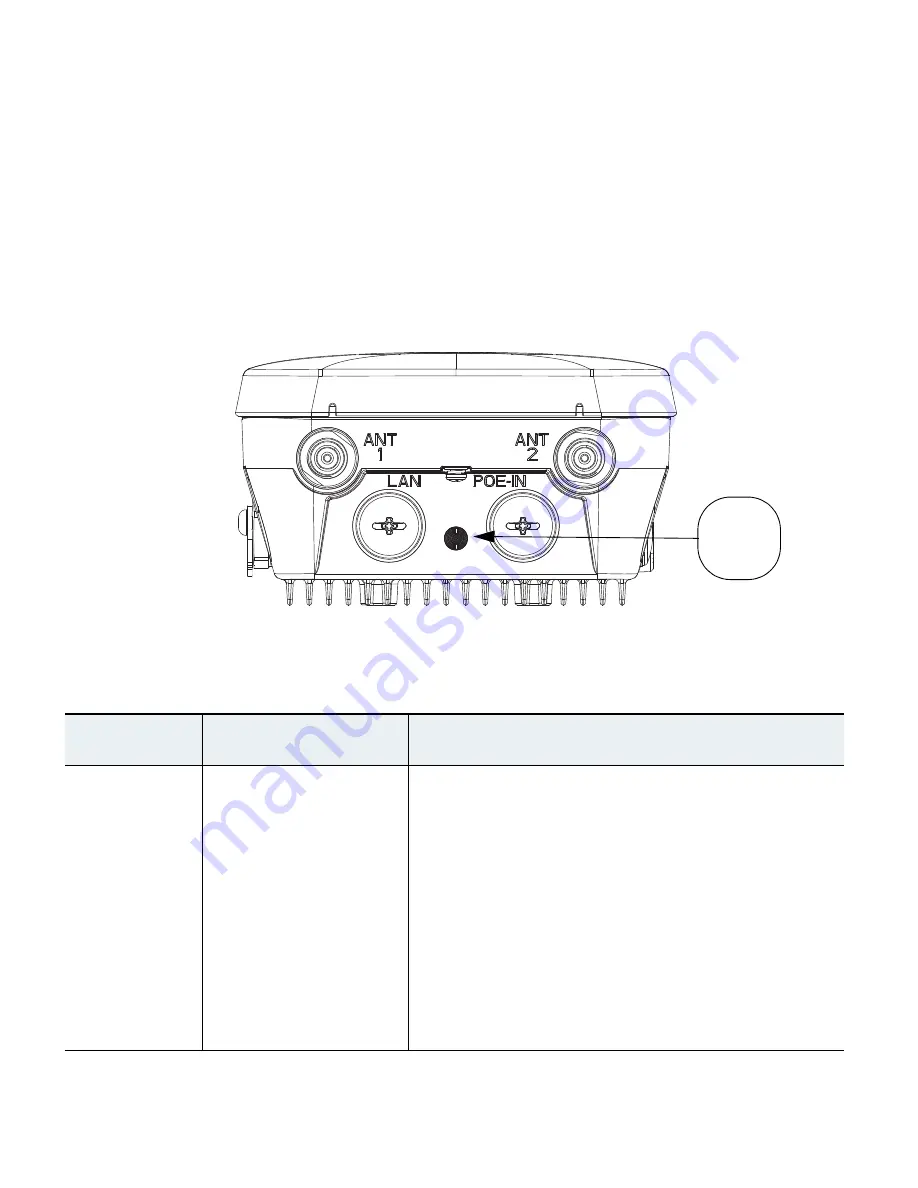
One LED is located between the LAN and PoE-In connectors. It indicates the status of the access point 
power, uplinks and radios. 

Figure 10

 identifies and describes the LED functions. 

Table 3

 provides 

additional LED signal information.

Figure 10

Access Point LEDs –Shown on the Bottom of AP 1532E

Table 3

Access Point LED Signals 

LED Message 
Type

Color

Meaning

Boot loader 
status sequence

Blinking 

Green

Boot loader status sequence:

DRAM memory test in progress

DRAM memory test OK

Board initialization in progress

Initializing FLASH file system

FLASH memory test OK

Initializing Ethernet

Ethernet OK

Starting Cisco IOS

Initialization successful

347848

LED
Indicator

Summary of Contents for Aironet 1530

Page 1: ...this Guide 2 Introduction to the Access Point 3 Unpacking the Access Point 4 Radio Configuration 5 Becoming Familiar With the Access Point 6 AP Pole Wall Mount 7 Preparing the Access Point 8 Deploying the Access Point 9 In Case of Difficulty 10 Declarations of Conformity and Regulatory Information 11 Warranty ...

Page 2: ...2 Created November 14 2014 78 21473 01 ...

Page 3: ...isco AP 1530 Series in the Search for a Specific Product field The Cisco 1530 Series Introduction page appears Step 6 Choose the appropriate link for the documentation you want to view or download General Safety Guidelines Warnings Safety warnings appear throughout this guide in procedures that may harm you if performed incorrectly A warning symbol precedes each warning statement The warnings belo...

Page 4: ... Contact the appropriate electrical inspection authority or an electrician if you are uncertain that suitable grounding is available Statement 366 Warning Read the installation instructions before connecting the system to the power source Statement 1004 Warning Only trained and qualified personnel should be allowed to install replace or service this equipment Statement 1030 Warning Ultimate dispos...

Page 5: ...work Intelligent wireless routing is provided by the Adaptive Wireless Path Protocol AWPP This enables each access point to identify its neighbors and intelligently choose the optimal path to the wired network by calculating the cost of each path in terms of signal strength and the number of hops required to get to a controller The access point is configured monitored and operated through a Cisco ...

Page 6: ...und lug Panduit PLCD6 10A L and screws with lock washers Plastic cable gland and rubber seal Weatherization tape and anti corrosion sealant Cisco product documentation and translated safety warnings Optional Equipment Depending on what you ordered the following optional equipment may be part of your shipment External antennas depending on which ones you purchased see 1532E Antennas section on page...

Page 7: ... patch 5 GHz AIR ANT5180V N 8 dBi OMNI AIR ANT5114P2M N 14 dBi dual polarized patch Non Cisco Antennas Cisco does not support any third party antennas RF connectivity and compliance of third party antennas is the customer s responsibility Cisco does not recommend any third party antennas and Cisco Technical Assistance Center will not be able to provide any support for third party antennas Cisco s ...

Page 8: ...MO radio operates in 2 4 GHz ISM band It supports up to 13 channels The 5 GHz MIMO radio operates in the UNII 2 band 5 25 5 35 GHz the UNII 2 Extended ETSI band 5 47 5 725 GHz and the upper ISM band 5 725 5 875 GHz It supports up to 16 channels Refer to the data sheet for the number of channels that are supported for each regulatory domain ...

Page 9: ... rubber seals to ensure the watertight integrity of the access point Liquid tight connectors and rubber seals are provided for all ports which can be installed prior to or after deploying the access point Figure 1 and Figure 3 shows the access point bottom and top connectors for model AP 1532I Figure 2 shows the bottom connectors for model AP 1532E Figure 4 and Figure 5 show the left and right sid...

Page 10: ...t Bottom Connectors AP 1532E Figure 3 Access Point Top Connectors AP 1532E 1 Antenna port 1 2 Antenna port 2 3 LAN port covered 4 PoE in port covered 1 Antenna port 4 covered 2 Antenna port 3 covered 347848 1 2 4 3 347847 1 2 ...

Page 11: ...de Connectors Both AP 1532 Models Figure 5 Access Point DC Power Connector and Ground Lug Both AP 1532 Models 1 Console Port and Reset button covered 1 DC power port covered 2 Ground lug location 3 Barcode label 347845 1 347846 1 2 3 ...

Page 12: ... for 8 levels in 3 dB steps It has three receivers that enables maximum ratio combining MRC The 5 GHz a n radio operates in the UNII 2 band 5 25 5 35 GHz UNII 2 Extended ETSI band 5 47 5 725 GHz and the upper ISM band 5 725 5 850 GHz It has two transmitters with a maximum total output power of 27 dBm depending on the regulatory domain The total maximum output power for the upper ISM band is 27 dBm...

Page 13: ...ed with 4 N type radio frequency RF connectors antenna ports 1 and 2 on the bottom of the unit for 2 GHz and antenna ports 3 and 4 on the top of the unit for 5 GHz for external antennas to support multiple input multiple output MIMO operation The antenna ports located of top of the 1532E are shown in Figure 3 The 1532E must always be operated with the appropriate external antennas attached Ports 1...

Page 14: ...E antennas can be mounted on a wall pole and or tower mounted See Antennas page 7 for a list of supported antennas Figure 7 Access Point Dual Band Omnidirectional Antennas Installed Only on AP 1532E 1 Antenna connected to antenna port 1 Type N connector TX RX 2 Antenna connected to antenna port 2 Type N connector TX RX 1 2 ...

Page 15: ...ly grounded using a customer supplied ground wire before power is applied Contact the appropriate electrical inspection authority or an electrician if you are uncertain that suitable grounding is available Statement 366 Warning Do not work on the system or connect or disconnect cables during periods of lightning activity Statement 1001 The 1532E access point supports these power sources DC power 2...

Page 16: ...upports an Ethernet uplink port PoE In The access point Ethernet uplink port uses an RJ 45 connector with weatherproofing to link the access point to the 10BASE T 100BASE T or 1000BASE T network The Ethernet cable is used to send and receive Ethernet data and to optionally supply inline 56 VDC power from the power injector Tip The access point senses the Ethernet and power signals and automaticall...

Page 17: ...le or tower mounted There are two optional mounting kits a fixed mounting kit AIR ACC1530 PMK1 and a pivoting mounting kit AIR ACC1530 PMK2 Warning Only trained and qualified personnel should be allowed to install replace or service this equipment Statement 1030 Warning Installation of the equipment must comply with local and national electric codes Statement 1074 When mounting an access point on ...

Page 18: ...t a 50 lb 22 7 kg static weight To mount the access point on a vertical wall follow these instructions Materials Required In Kit Ground lug and screws provided with access point Yes Wall Mount Bracket Yes Four M6 x 12 mm Hex head Bolts Yes Two stainless steel band clamps adjustable 2 5 51 mm 127 mm Yes Two stainless steel band clamps adjustable 5 8 127 mm 203 mm Yes Crimping tool for ground lug Pa...

Page 19: ...g surface Note If necessary use suitable screw anchors and an exterior grade plywood backboard to mount the access point to stucco cement or drywall Step 3 Screw an M6 x12 mm bolt into each of the four support bolt holes on the back of the access point Do not screw the bolt all the way in leave approximately a 0 13 inch 3 3 mm space Step 4 Position the four bolts on the access point into the keyho...

Page 20: ...ole To mount the access point onto a vertical pole or streetlight pole follow these steps Step 1 Select a mounting location on the pole to mount the access point You can attach the access point to any pole with a diameter from 2to 8 inches 5 1 to 20 1 cm Materials Required In Kit One wall mount bracket Yes Four M6 x12mm hex head bolts Yes Two stainless steel band clamps adjustable 2 5 51 127 mm Ye...

Page 21: ...p 4 Screw an M6 bolt into each of the four bolt holes on the back side of the access point Do not screw the bolt in all the way Leave a gap of about 0 13 3 3mm Step 5 Position the four bolts on the access point into the bracket keyhole slots Check to be sure that the access point is properly seated in the slots See Figure 9 Note The access point should be positioned with the LEDs on the bottom to ...

Page 22: ...22 Figure 9 AP and Fixed Mount Kit Installed on a Pole 1 Metal Band Strap 2 Mounting Slots 3 Pole 351492 1 2 3 ...

Page 23: ...e strip the insulation as required for the grounding lug Step 2 Use the appropriate crimping tool to crimp the bare 6 AWG copper ground wire to the supplied grounding lug Note The grounding lug and hardware used must comply with local and national electrical codes Step 3 Open the electrical joint compound supplied and apply a liberal amount over the metal surface where the ground strap screw holes...

Page 24: ... For information on conducting a site survey prior to installing the access point see the Cisco Aironet 1530 Series Outdoor Access Point Hardware Installation Guide Avoiding Damage to Radios in a Testing Environment The radios on outdoor units bridges have higher transmit power levels than radios on indoor units access points When you test radios in a link you must avoid exceeding the maximum rece...

Page 25: ...antenna port of another access point without using an RF attenuator If you connect antenna ports you must not exceed the maximum survivable receive level of 0 dBm Never exceed 0 dBm or damage to the access point can occur Using attenuators combiners and splitters having a total of at least 60 dB of attenuation ensures that the receiver is not damaged and PER performance is not degraded Before You ...

Page 26: ...er to which the access point will associate is properly configured by performing the following operations Verify the wireless LAN controller software version Record the access point BVI MAC address MAC address is located on the label on the side of the unit Enter the access point BVI MAC address to the wireless LAN controller filter list Recording the Access Point MAC Address Use a text file to re...

Page 27: ...ield You can also use the config macfilter add command to add a MAC filter entry to the controller Step 6 Select a WLAN ID or Any WLAN from the WLAN ID pop up menu Step 7 Enter a description 32 characters maximum of the access point in the Description field Step 8 Choose an interface from the Interface Name pop up menu Step 9 Click Apply Step 10 Repeat this process to add other access points to th...

Page 28: ...ologies_configuration_example09186a0080871 4fe shtml DHCP Option 43 server implementation information for Cisco IOS is available at cisco com at the following URL http www cisco com en US docs wireless technology controller deployment guide dep html wp106 8287 Note In DHCP Option 43 you should use the IP address of the controller management interface Note DHCP Option 43 is limited to one access po...

Page 29: ...he IP address of the DNS server such as 10 0 10 2 Step 3 Add the Option 60 line using the following syntax option 60 ascii VCI string For the VCI string use the value from Configuring DHCP Option 43 page 28 The quotation marks must be included Step 4 Add the option 43 line using the following syntax option 43 hex hex string The hex string is assembled by concatenating the TLV values shown below Ty...

Page 30: ...r This is the same operation as other Cisco controller based APs For Autonomous mode the user should take the following steps Step 1 Power the AP and connect to the console Step 2 From the Command Line enter AP capwap ap autonomous means privileged EXEC mode Step 3 The system will respond with Convert to Autonomous image Proceed yes No Step 4 Type yes to confirm Step 5 The AP will then re boot and...

Page 31: ...t and Documentation page at cisco com Follow these steps to contact the Technical Assistance Center on cisco com Step 1 Open your browser and go to http www cisco com Step 2 Click Support The Support page appears Step 3 Choose the link that best serves your support requirements Note Click My Tech Support if you are a registered user Step 4 Follow the instructions on the page Troubleshooting Cautio...

Page 32: ...y and tertiary controllers must allow IP packet fragments Before deploying your mesh access points ensure that the following has been done Your controllers are connected to switch ports that are configured as trunk ports Your mesh access points are connected to switch ports that are configured as untagged access ports A DHCP server is reachable by your mesh access points and has been configured wi...

Page 33: ...information Figure 10 Access Point LEDs Shown on the Bottom of AP 1532E Table 3 Access Point LED Signals LED Message Type Color Meaning Boot loader status sequence Blinking Green Boot loader status sequence DRAM memory test in progress DRAM memory test OK Board initialization in progress Initializing FLASH file system FLASH memory test OK Initializing Ethernet Ethernet OK Starting Cisco IOS Initia...

Page 34: ...icate any of the following Environment variable failure Bad MAC address Ethernet failure during image recovery Boot environment failure No Cisco image file Boot failure Cisco IOS errors Solid Red There has been a software failure a disconnect then reconnect of the unit power may resolve the issue Cycling through Red Green Amber and Off This is a general warning of insufficient inline power Associa...

Page 35: ... Rapidly cycling through Red Green Amber and Off This status indicates that the Access Point location command has been invoked Blinking Red This status indicates that an Ethernet link is not operational Alignment Mode Color Signal Level dBm Solid Green 44 Fast blinking Green 47 to 44 Medium blinking Green 50 to 47 Solid Amber 53 to 50 Fast blinking Amber 57 to 53 Medium blinking Amber 60 to 57 Slo...

Page 36: ...d access point appears in the Summary page of the controller configure the access point with an IP address If you are using a static IP address on the access point and plan on redeploying the access point on another subnet perform a clear config command from the controller for that access point while it is joined before you remove it from the network Verifying the Controller MAC Filter List Prior ...

Page 37: ...Appendix Declarations of Conformity and Regulatory Information in the Cisco Aironet 1530 Series Outdoor Access Point Hardware Installation Guide 11 Warranty Cisco Aironet 1530 Series Outdoor Mesh Access Points come with a one year warranty For more details visit http www cisco com go warranty and look up the 1530 series access points in the Warranty Finder tool ...

Page 38: ...38 ...

Page 39: ...39 ...

Page 40: ...a partnership relationship between Cisco and any other company 1110R 2013 Cisco Systems Inc All rights reserved Printed in the USA on recycled paper containing 10 postconsumer waste 78 21473 01 Americas Headquarters Cisco Systems Inc San Jose CA Asia Pacific Headquarters Cisco Systems USA Pte Ltd Singapore Europe Headquarters Cisco Systems International BV Amsterdam The Netherlands Cisco has more ...

Reviews: