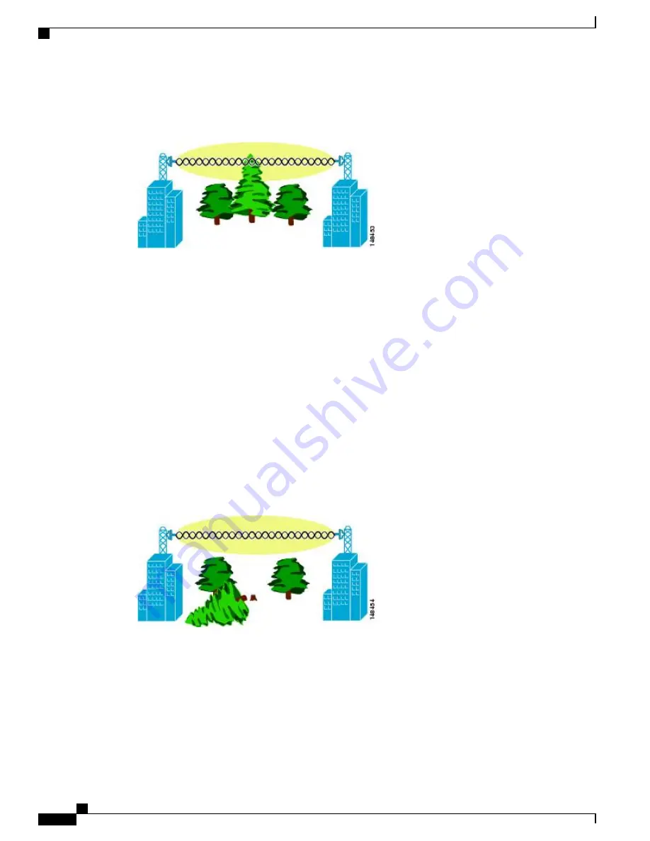
Figure 25: Typical Obstructions in a Fresnel Zone, on page 64
illustrates an obstructed Fresnel zone.
Figure 25: Typical Obstructions in a Fresnel Zone
It is possible to calculate the radius of the Fresnel zone (in feet) at any particular distance along the path using
the following equation:
F1 = 72.6 X square root (d/4 x f)
where
F1 = the first Fresnel zone radius in feet
D = total path length in miles
F = frequency (GHz)
Normally, 60 percent of the first Fresnel zone clearance is recommended, so the above formula for 60 percent
Fresnel zone clearance can be expressed as follows:
0.60 F1= 43.3 x square root (d/4 x f)
These calculations are based on a flat terrain.
Figure 26: Removing Obstructions in a Fresnel Zone, on page 64
shows the removal of an obstruction in the
Fresnel zone of the wireless signal.
Figure 26: Removing Obstructions in a Fresnel Zone
Fresnel Zone Size in Wireless Mesh Deployments
To give an approximation of size of the maximum Fresnel zone to be considered, at a possible minimum
frequency of 4.9 GHz, the minimum value changes depending on the regulatory domain. The minimum figure
quoted is a possible band allocated for public safety in the USA, and a maximum distance of one mile gives
a Fresnel zone of clearance requirement of 9.78 ft = 43.3 x SQR(1/(4*4.9)). This clearance is relatively easy
to achieve in most situations. In most deployments, distances are expected to be less than one mile, and the
Cisco Mesh Access Points, Design and Deployment Guide, Release 7.3
64
OL-27593-01
Site Preparation and Planning
Fresnel Zone Size in Wireless Mesh Deployments


