background image


5-6

Cisco Aironet 1300 Series Outdoor Access Point/Bridge Hardware Installation Guide

OL-5048-02

Chapter 5      Configuring the Access Point/Bridge for the First Time

Assigning Basic Settings

Step 4

Click 

Express Setup

. The Express Setup page displays. 

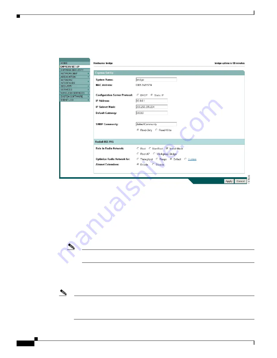
Figure 5-2

 shows the Express Setup page.

Figure 5-2

Express Setup Page

Step 5

Enter the configuration settings you obtained from your system administrator. The configurable settings 
include:

System Name 

or

 Host Name

—The system name or host name, while not an essential setting, helps 

identify the access point/bridge on your network. The name appears in the titles of the management 
system pages. 

Configuration Server Protocol

—Click the button that matches the network’s method of IP address 

assignment.

DHCP

—IP addresses are automatically assigned by your network’s DHCP server.

Note

When DHCP is enabled, the IP Address, Subnet Mask, and Default Gateway fields indicate 

Negotiated by DHCP

.

Static IP

—The access point/bridge uses a static IP address that you enter in the IP address field.

IP Address

—Use this setting to assign or change the access point/bridge’s IP address. If DHCP is 

enabled for your network, leave this field blank. 

Note

If the access point/bridge’s IP address changes while you are configuring the access point/bridge 
using the web-browser interface or a Telnet session over the wired LAN, you lose your 
connection to the access point/bridge. If you lose your connection, reconnect to the access 
point/bridge using its new IP address. 

Summary of Contents for AIR-BR1310G-A-K9 - Aironet 1310 Outdoor Access Point/Bridge

Page 1: ... 170 West Tasman Drive San Jose CA 95134 1706 USA http www cisco com Tel 408 526 4000 800 553 NETS 6387 Fax 408 526 4100 Cisco Aironet 1300 Series Outdoor Access Point Bridge Hardware Installation Guide April 2005 Text Part Number OL 5048 02 ...

Page 2: ...asures Turn the television or radio antenna until the interference stops Move the equipment to one side or the other of the television or radio Move the equipment farther away from the television or radio Plug the equipment into an outlet that is on a different circuit from the television or radio That is make certain the equipment and the television or radio are on circuits controlled by differen...

Page 3: ...ducts xiv Obtaining Technical Assistance xiv Cisco Technical Support Website xv Locating the Product Serial Number xv Submitting a Service Request xvi Definitions of Service Request Severity xvii Obtaining Additional Publications and Information xvii C H A P T E R 1 Overview 1 1 Key Features 1 2 Power 1 3 Integrated Antenna 1 3 External Antenna 1 4 Ethernet Ports 1 4 Enclosure 1 4 Connectors 1 4 L...

Page 4: ... Guidelines 2 5 Site Surveys 2 6 Unpacking the Access Point Bridge 2 6 Package Contents 2 6 Before Beginning the Installation 2 7 Installation Summary 2 9 C H A P T E R 3 Mounting and Alignment Overview 3 1 Mounting the Access Point Bridge 3 2 Mounting Hardware 3 2 Window Mounting 3 3 Multi Function Mount 3 3 Access Point Bridge Bracket 3 4 Mast Bracket 3 4 LEDs 3 5 Aligning the Bridge Antenna Usi...

Page 5: ...put Power Level 5 9 Configuring Basic Security Settings 5 9 Understanding Express Security Settings 5 11 Using VLANs 5 11 Express Security Types 5 11 Express Security Limitations 5 12 Using the Express Security Page 5 13 Finding the IP Address Using the CLI 5 13 Assigning an IP Address Using the CLI 5 14 Using a Telnet Session to Access the CLI 5 14 C H A P T E R 6 Using the Command Line Interface...

Page 6: ...6 Default SSID and Radio Behavior 7 6 Enabling the Radio Interface 7 7 SSID 7 7 Security Settings 7 8 Antenna Alignment 7 8 Running the Carrier Busy Test 7 8 Running the Ping or Link Test 7 9 Resetting the Access Point Bridge to the Default Configuration 7 10 Using the Web Browser Interface 7 10 Using the CLI 7 10 Reloading the Access Point Bridge Image 7 11 Web Browser Interface 7 11 Browser HTTP...

Page 7: ...formity with Regard to the R TTE Directive 1999 5 EC B 3 Declaration of Conformity for RF Exposure B 5 Guidelines for Operating Cisco Aironet Access Points and Bridges in Japan B 5 Japanese Translation B 5 English Translation B 5 Administrative Rules for Cisco Aironet Access Points and Bridges in Taiwan B 6 All Access Points and Bridges B 6 Chinese Translation B 6 English Translation B 6 Declarati...

Page 8: ... Cisco Aironet 1300 Series Outdoor Access Point Bridge Hardware Installation Guide OL 5048 02 A P P E N D I X F Load Dump Protection for Transportation Vehicles F 1 Load Dump Protection F 1 G L O S S A R Y I N D E X ...

Page 9: ... concepts Organization This guide contains the following sections Chapter 1 Overview describes the major components features and specifications of the access point bridge Chapter 2 Installation Overview provides warnings safety information and information needed before you begin the installation of your access point bridge system Chapter 3 Mounting and Alignment Overview provides an overview of co...

Page 10: ...aterials not contained in this manual Caution Means reader be careful In this situation you might do something that could result in equipment damage or loss of data Warning This warning symbol means danger You are in a situation that could cause bodily injury Before you work on any equipment be aware of the hazards involved with electrical circuitry and be familiar with standard practices for prev...

Page 11: ... avvertenze di sicurezza Advarsel Dette varselsymbolet betyr fare Du befinner deg i en situasjon som kan føre til personskade Før du utfører arbeid på utstyr må du være oppmerksom på de faremomentene som elektriske kretser innebærer samt gjøre deg kjent med vanlig praksis når det gjelder å unngå ulykker Hvis du vil se oversettelser av de advarslene som finnes i denne publikasjonen kan du se i vedl...

Page 12: ... instructions for mounting the unit and aligning the antenna Cisco IOS Command Reference for Cisco Aironet Access Points and Bridges describes the IOS commands supported by Cisco Aironet access points and bridges This document is available on the Cisco CCO web site at the following URL http www cisco com univercd cc td doc product wireless index htm Release Notes for Cisco Aironet 1300 Series Outd...

Page 13: ...US partner ordering Cisco Marketplace http www cisco com go marketplace Ordering Documentation You can find instructions for ordering documentation at this URL http www cisco com univercd cc td doc es_inpck pdi htm You can order Cisco documentation in these ways Registered Cisco com users Cisco direct customers can order Cisco product documentation from the Ordering tool http www cisco com en US p...

Page 14: ...them and we strive to correct all vulnerabilities quickly If you think that you might have identified a vulnerability in a Cisco product contact PSIRT Emergencies security alert cisco com Nonemergencies psirt cisco com Tip We encourage you to use Pretty Good Privacy PGP or a compatible product to encrypt any sensitive information that you send to Cisco PSIRT can work from encrypted information tha...

Page 15: ...uct serial number before submitting a web or phone request for service You can access the CPI tool from the Cisco Technical Support Website by clicking the Tools Resources link under Documentation Tools Choose Cisco Product Identification Tool from the Alphabetical Index drop down list or click the Cisco Product Identification Tool link under Alerts RMAs The CPI tool offers three search options by...

Page 16: ...e in which your network is minimally impaired or for which you require product information After you describe your situation the TAC Service Request Tool provides recommended solutions If your issue is not resolved using the recommended resources your service request is assigned to a Cisco TAC engineer The TAC Service Request Tool is located at this URL http www cisco com techsupport servicereques...

Page 17: ...merchandise Visit Cisco Marketplace the company store at this URL http www cisco com go marketplace Cisco Press publishes a wide range of general networking training and certification titles Both new and experienced users will benefit from these publications For current Cisco Press titles and other information go to Cisco Press at this URL http www ciscopress com Packet magazine is the Cisco Syste...

Page 18: ...int Bridge Hardware Installation Guide OL 5048 02 Preface Obtaining Additional Publications and Information World class networking training is available from Cisco You can view current offerings at this URL http www cisco com en US learning index html ...

Page 19: ...antenna gains as well as coverage patterns It supports point to point and multipoint bridging configurations The access point bridge can also be configured to operate as an access point or as a workgroup bridge When placed in access point mode the unit supports wireless IEEE 802 11b and IEEE 802 11g client devices When placed into workgroup bridge mode the unit provides a wireless connection for r...

Page 20: ...ax 100 Mbps Ethernet ports Four LEDs Inline power over dual coax cables Console serial interface on power injector Receive Signal Strength Indicator RSSI LED patterns for easy antenna alignment Control using Cisco IOS commands Internet browser SNMP or serial interface on power injector Three operating modes Bridge mode Access point mode Workgroup bridge mode Figure 1 1 Access Point Bridge Configur...

Page 21: ...ble interface to the access point bridge The power injector is available in two models Cisco Aironet Power Injector LR2 standard version included with the bridge 48 VDC input power Uses the 48 VDC power module included with the bridge Cisco Aironet Power Injector LR2T optional transportation version 12 to 40 VDC input power DC power supplied from a vehicle battery Note The power injector and the p...

Page 22: ...onsible for installing and configuring the unit is a suitable professional installer Following installation access to the unit should be password protected by the network administrator to maintain regulatory compliance Ethernet Ports The access point bridge dual coax Ethernet ports consists of a pair of 75 ohm F type connectors linking the unit to your 100BASE T Ethernet LAN through the power inje...

Page 23: ... alignment conditions status radio activity and Ethernet activity see Figure 1 3 Figure 1 3 LEDs 1 Ground lug mounting screws 3 Mounting posts 2 Left antenna connector external antenna access point bridge configuration only 4 LEDs Primary right antenna connector external antenna access point bridge configuration only 5 Dual coax Ethernet ports F Type connectors 117060 1 2 3 4 5 R Radio LED R E Eth...

Page 24: ...he unit assumes a non root bridge role If the unit is unable to associate with another Cisco Aironet root bridge within 60 seconds the unit assumes a root bridge role You can also pre configure the access point bridge into root bridge or non root bridge modes and avoid the 60 second automatic detection phase Root Specifies that the access point bridge is operating as a root bridge and connects dir...

Page 25: ...is classified as a root bridge and the other bridge is classified as a non root bridge Figure 1 4 Point to Point Bridge Configuration Port Aggregation or Redundancy Bridge Configuration The port aggregation or redundancy bridge configuration Figure 1 5 is used to provide increased bandwidth or backup redundancy communications between two LANs Port aggregation or increased bandwidth occurs when bot...

Page 26: ...the root bridge Figure 1 6 Point to Multipoint Bridge Configuration Access Point Configuration When configured in access point mode the unit can support remote workgroup bridges and local wireless client devices see Figure 1 7 The access point bridge defaults to a root access point role Figure 1 7 Access Point Configuration The access point configuration allows the wireless devices and the Etherne...

Page 27: ... Ethernet enabled devices to pass Ethernet traffic to and from the main LAN using the workgroup bridge Figure 1 9 Workgroup Bridge Configuration 2 In Figure 1 9 the unit is configured in workgroup bridge mode and is associated to a Cisco Aironet root bridge as a wireless bridge device This configuration allows the Ethernet enabled devices pass Ethernet traffic to and from the main LAN using the wo...

Page 28: ...1 10 Cisco Aironet 1300 Series Outdoor Access Point Bridge Hardware Installation Guide OL 5048 02 Chapter 1 Overview Network Configuration Examples ...

Page 29: ...ter provides warnings safety information and information needed before you begin the installation of your access point bridge system This chapter includes the following sections Safety Warnings page 2 2 Safety Information page 2 3 Unpacking the Access Point Bridge page 2 6 Before Beginning the Installation page 2 7 Installation Summary page 2 9 ...

Page 30: ...lified for such use Statement 245B Warning In order to comply with international radio frequency RF exposure limits dish antennas should be placed at a minimum of 8 7 inches 22 cm from the bodies of all persons Other antennas should be placed a minimum of 7 9 inches 20 cm from the bodies of all persons Statement 346 Warning Do not work on the system or connect or disconnect cables during periods o...

Page 31: ...r service this equipment Statement 1030 Vehicle Bridge Installations The following warnings apply to vehicle bridge installations Warning A readily accessible two poled disconnect device must be incorporated in the fixed wiring Statement 1022 Warning Connect the unit only to DC power source that complies with the safety extra low voltage SELV requirements in IEC 60950 based safety standards Statem...

Page 32: ...d Remember electric power lines and phone lines look alike For your safety assume that any overhead line can kill you 3 Call your electric power company Tell them your plans and ask them to come look at your proposed installation This is a small inconvenience considering your life is at stake 4 Plan your installation carefully and completely before you begin Successful raising of a mast or tower i...

Page 33: ...ional Electrical Code U S Canadian Electrical Code Part I CSA 22 1 Canada and if local or national electrical codes are not available refer to IEC 364 Part 1 through 7 other countries Note The grounding block is not required for indoor installations of the access point bridge Installation Guidelines Because the access point bridge is a radio device it is susceptible to common causes of interferenc...

Page 34: ...censed radio systems Physical environment Clear or open areas provide better radio range than closed or filled areas Obstructions Physical obstructions such as buildings trees or hills can hinder performance of wireless devices Avoid locating the devices in a location where there is an obstruction between the sending and receiving antennas Unpacking the Access Point Bridge Follow these steps to un...

Page 35: ...ntains these items Wall mount bracket with 4 mounting bolts and washers Two sub mini RG 59 coax cables 12 in or 30 5 cm The optional power injector for transportation vehicles Power injector LR2T unit Before Beginning the Installation Before you begin the installation process please carefully review the following list of figures to become familiar with the system components connectors indicators c...

Page 36: ...Layout Figure 2 3 Power Injector Indicators and Connectors 1 Grounding studs 4 LEDs 2 Antenna connectors 5 Dual coax Ethernet ports F Type connectors 3 Mounting lugs 117060 1 2 3 4 5 1 Dual coax Ethernet ports F Type connectors 4 Ethernet LAN port RJ 45 connector 2 Power LED 5 Console serial port RJ 45 connector 3 Power jack 117189 C I S C O A I R O N E T P O W E R I N J E C T O R 5 4 1 1 3 2 ...

Page 37: ...antenna access point bridge unit and the external antenna must be professionally installed The network administrator or other IT professional responsible for installing and configuring the unit is a suitable professional installer Following installation access to the unit should be password protected by the network administrator to maintain regulatory compliance During the installation of the acce...

Page 38: ...electrician if you are uncertain that suitable grounding is available Statement 1024 Connect a ground wire to the access point bridge use the access point bridge ground lug For outdoor installations connect the dual coax Ethernet cables to the grounding block and to the access point bridge For indoor installations connect the dual coax cables directly to the access point bridge Tip You can connect...

Page 39: ... Installation Summary Seal all external connectors with special weather sealing material Configure security and other access point bridge options For additional information refer to the Cisco IOS Software Configuration Guide for Cisco Aironet Bridges or to the Cisco IOS Software Configuration Guide for Cisco Aironet Access Points ...

Page 40: ...2 12 Cisco Aironet 1300 Series Outdoor Access Point Bridge Hardware Installation Guide OL 5048 02 Chapter 2 Installation Overview Installation Summary ...

Page 41: ...g and Alignment Overview This chapter provides an overview of the access point bridge mounting and bridge antenna alignment The following sections are included in this chapter Mounting the Access Point Bridge page 3 2 Mounting Hardware page 3 2 LEDs page 3 5 Aligning the Bridge Antenna Using RSSI LED Indications page 3 7 ...

Page 42: ...stration or other IT professional responsible for installing and configuring the unit is a suitable professional installer Following installation access to the unit should be password protected by the network administrator to maintain regulatory compliance The following warning applies to outdoor and vehicle installations Warning Only trained and qualified personnel should be allowed to install re...

Page 43: ...ack of the unit Mast bracket attaches to the mast tower or roof mount The multi function mount permits easy azimuth and elevation adjustments for bridge antenna alignment The basic mounting procedure is shown below 1 Mount the access point bridge bracket to the mounting lugs on the access point bridge 2 Mount the mast bracket to the tower or mast using the supplied U bolts or appropriately sized u...

Page 44: ...es the remote antenna The integrated access point bridge antenna is vertically polarized All access point bridges must use the same antenna polarization for best operation Mast Bracket The mast bracket attaches to a mast or tower support and is used to secure the access point bridge see Table 3 1 Note The U bolts provided with the roof mounting kit support mast diameters up to 1 75 in 44 5 mm For ...

Page 45: ...nt bridge running Cisco IOS 12 3 4 JA is initially powered up the unit defaults to a root access point with the radio disabled and no default SSID To allow client associations you must configure an SSID and enable the radio interface refer to the Configuring the Access Point Bridge for the First Time section on page 5 1 When the access point bridge running Cisco IOS 12 3 2 JA2 and earlier is initi...

Page 46: ...ured bridge mode The unit attempts to associate with a remote bridge in the configured mode either root or non root Because there are no timeouts it is easier to align the antenna Preconfigured access point or workgroup bridge modes the bridge Install LED does not operate Table 3 2 Install LED Status Install LED Status Bridge State Off Self test Startup Amber blinking Non root searching Not associ...

Page 47: ...s the maximum level received After 20 seconds have elapsed the Install LED turns amber and the Ethernet status and radio LEDs display the relative RSSI levels compared to the maximum received The RSSI LED indications are shown in Table 3 3 Note For the signal level dBm a smaller number represents a stronger signal because the signal level is given as a negative value When using LEDs to maximize th...

Page 48: ...3 8 Cisco Aironet 1300 Series Outdoor Access Point Bridge Hardware Installation Guide OL 5048 02 Chapter 3 Mounting and Alignment Overview Aligning the Bridge Antenna Using RSSI LED Indications ...

Page 49: ...erface that you can use to configure the access point bridge The web browser interface contains management pages that you use to change access point bridge settings upgrade firmware and monitor and configure other wireless devices on the network This chapter contains these sections Using the Web Browser Interface Management Pages page 4 2 Connecting Locally to the Ethernet Port page 4 5 ...

Page 50: ...ar to browse to other management pages and you use the configuration action buttons to save or cancel changes to the configuration Note The access point bridge web browser interface uses Windows Internet Explorer version 6 0 or higher or Netscape Communicator version 7 0 or higher on your Windows based PC Note Changes are applied only when you click Apply It s important to remember that clicking y...

Page 51: ...plays a list of all devices on your wireless LAN listing their system names network roles and parent client relationships Network Interfaces Displays status and statistics for the Ethernet and radio interfaces and provides links to configuration pages for each interface Security Displays a summary of security settings and provides links to security configuration pages Services Displays status for ...

Page 52: ...rs and the fields in which you cannot use them Using Online Help Click the help icon at the top of any page in the web browser interface to display online help Figure 4 2 shows the print and help icons Figure 4 2 Print and Help Icons When a help page appears in a new browser window use the Select a topic drop down menu to display the help index or instructions for common configuration tasks Table ...

Page 53: ...le Your PC and the access point bridge must be configured with compatible IP addresses and subnet masks to be able to communicate on the Ethernet interface If the access point bridge is running Cisco IOS Release 12 2 15 JA or earlier and is configured with default values you must manually assign your PC an IP address from 10 0 0 31 to 10 0 0 40 If the access point bridge is running Cisco IOS Relea...

Page 54: ...4 6 Cisco Aironet 1300 Series Outdoor Access Point Bridge Hardware Installation Guide OL 5048 02 Chapter 4 Using the Web Browser Interface Connecting Locally to the Ethernet Port ...

Page 55: ...to complete the initial configuration and then use the CLI to enter additional settings for a more detailed configuration This chapter contains these sections Before You Start page 5 2 Resetting the Access Point Bridge to Default Settings page 5 2 Default IP Address Behavior page 5 2 Default SSID and Default Role page 5 3 Obtaining and Assigning an IP Address page 5 3 Connecting to the Access Poin...

Page 56: ...orer version 6 0 or higher or Netscape Communicator version 7 0 or higher Step 2 Enter the access point bridge IP address in the browser address line and press Enter An Enter Network Password window displays Step 3 Enter your username in the User Name field The default username is Cisco Step 4 Enter the access point bridge password in the Password field and press Enter The default password is Cisc...

Page 57: ...int bridge defaults to the Root AP mode and no default SSID configured Obtaining and Assigning an IP Address To browse to the access point bridge s Express Setup page you must either obtain or assign the access point bridge s IP address using one of the following methods Connect to the access point bridge console port and assign a static IP address refer to the Using the Power Injector s Console P...

Page 58: ... 15 JA or earlier and is configured with default values you must manually assign your PC an IP address from 10 0 0 31 to 10 0 0 40 b If the access point bridge is running Cisco IOS Release 12 3 2 JA2 or later and is configured with default values you must manually assign a temporary static IP address to the access point bridge and manally configure your PC with a compatible IP address and subnet m...

Page 59: ...you can browse to its Express Setup page and perform an initial configuration Follow these steps Step 1 Browse to the access point bridge IP address An Enter Network Password window displays Step 2 Enter the case sensitive username Cisco in the Username field Step 3 Enter the case sensitive password Cisco in the Password field and press Enter The Summary Status page displays which is the access po...

Page 60: ...iguration Server Protocol Click the button that matches the network s method of IP address assignment DHCP IP addresses are automatically assigned by your network s DHCP server Note When DHCP is enabled the IP Address Subnet Mask and Default Gateway fields indicate Negotiated by DHCP Static IP The access point bridge uses a static IP address that you enter in the IP address field IP Address Use th...

Page 61: ...root bridge modes and avoid the 60 second automatic detection phase Root Specifies that the unit is operating as a root bridge and connects directly to the main Ethernet LAN network In this mode the unit accepts associations from other Cisco Aironet non root bridges and wireless client devices Non root Specifies that the unit is operating as a non root bridge and connects to a remote LAN network a...

Page 62: ...ater System Name or Host Name bridge ap Configuration Server Protocol DHCP DHCP IP Address Assigned by DHCP1 default setting if DHCP is disabled the default setting is 10 0 0 1 1 After a static IP address is assigned or the role is changed from Install the SSID is automatically changed to tsunami Assigned by DHCP by default2 2 If an access point bridge running Cisco IOS Release 12 3 2 JA2 or later...

Page 63: ...rowser Adjusting Output Power Level Your access point bridge s output power level might require adjustment under the following conditions The access point bridge s output power level must be reduced when using the 15 dBi sector or the 21 dBi dish antenna refer to Maximum Power Levels and Antenna Gains section on page D 3 Your regulatory domain may limit the equivalent isotropic radiated power EIRP...

Page 64: ...or Access Point Bridge Hardware Installation Guide OL 5048 02 Chapter 5 Configuring the Access Point Bridge for the First Time Configuring Basic Security Settings Figure 5 3 shows the Express Security page Figure 5 3 Express Security Page ...

Page 65: ...tings WEP and ciphers apply to an interface such as the radio and you cannot use more than one encryption setting on an interface For example when you create an SSID with static WEP with VLANs disabled you cannot create additional SSIDs with WPA authentication because they use different encryption settings If you find that the security setting for an SSID conflicts with another SSID you can delete...

Page 66: ...Security SSID Manager page You cannot configure combinations of authentication types on the same SSID for example MAC address authentication and EAP authentication To configure combinations of authentication types use the Security SSID Manager page Note For detailed information about security and security settings refer to the Cisco IOS Software Configuration Guide for Cisco Aironet Access Points ...

Page 67: ...ity setting for the SSID The settings are listed in order of robustness from No Security to WPA which is the most secure setting If you select Static WEP Key choose the key number and encryption key size and enter the encryption key 10 hexidecimal characters for 40 bit keys or 26 hexidecimal characters for 128 bit keys If you select EAP Authentication or WPA enter the IP address and shared secret ...

Page 68: ...minal application Check your PC operating instructions for detailed instructions for your operating system Step 1 Select Start Programs Accessories Telnet If Telnet is not listed in your Accessories menu select Start Run type Telnet in the entry field and press Enter Step 2 When the Telnet window displays click Connect and select Remote System Note In Windows 2000 the Telnet window does not contai...

Page 69: ...ng to the Console Serial Port page 6 2 Using a Telnet Session to Open the CLI page 6 3 IOS Command Modes page 6 4 Getting Help page 6 5 Abbreviating Commands page 6 5 Using no and default Forms of Commands page 6 5 Understanding CLI Messages page 6 6 Using Command History page 6 6 Using Editing Features page 6 8 Searching and Filtering Output of show and more Commands page 6 10 Assigning an IP Add...

Page 70: ...le Step 2 Set up a terminal emulator to communicate with the access point bridge Use the following settings for the terminal emulator connection 9600 baud 8 data bits no parity 1 stop bit and no flow control Step 3 When the terminal emulator is activated press Enter An Enter Network Password window appears Step 4 Enter your username in the User Name field The default username is Cisco Step 5 Enter...

Page 71: ...Step 2 When the Telnet window appears click Connect and select Remote System Note In Windows 2000 the Telnet window does not contain drop down menus To start the Telnet session in Windows 2000 type open followed by the access point bridge s IP address Step 3 In the Host Name field type the access point bridge s IP address and click Connect Using Secure Shell to Open the CLI Secure Shell Protocol i...

Page 72: ...e configuration these commands are stored and used when the access point bridge reboots To access the various configuration modes you must start at global configuration mode From global configuration mode you can enter interface configuration mode and line configuration mode Table 6 1 describes the main command modes how to access each one the prompt you see in that mode and how to exit the mode T...

Page 73: ...or function or reverse the action of a command For example the no shutdown interface configuration command reverses the shutdown of an interface Use the command without the keyword no to re enable a disabled feature or to enable a feature that is disabled by default Table 6 2 Help Summary Command Purpose help Obtains a brief description of the help system in any command mode abbreviated command en...

Page 74: ...sts You can customize the command history feature to suit your needs as described in these sections Changing the Command History Buffer Size page 6 7 Recalling Commands page 6 7 Disabling the Command History Feature page 6 7 Table 6 3 Common CLI Error Messages Error Message Meaning How to Get Help Ambiguous command show con You did not enter enough characters for your access point bridge to recogn...

Page 75: ... 4 Disabling the Command History Feature The command history feature is automatically enabled To disable the feature during the current terminal session enter the terminal no history privileged EXEC command To disable command history for the line enter the no history line configuration command Table 6 4 Recalling Commands Action Result Press Ctrl P or the up arrow key 1 1 The arrow keys function o...

Page 76: ...e configuration mode br config line no editing Editing Commands Through Keystrokes Table 6 5 shows the keystrokes that you need to edit command lines Table 6 5 Editing Commands Through Keystrokes Capability Keystroke Purpose Move around the command line to make changes or corrections Ctrl B or the left arrow key1 Move the cursor back one character Ctrl F or the right arrow key1 Move the cursor for...

Page 77: ...command line Ctrl U or Ctrl X Delete all characters from the cursor to the beginning of the command line Ctrl W Delete the word to the left of the cursor Esc D Delete from the cursor to the end of the word Capitalize or lowercase words or capitalize a set of letters Esc C Capitalize at the cursor Esc L Change the word at the cursor to lowercase Esc U Capitalize letters from the cursor to the end o...

Page 78: ... 2 5 255 255 255 0 131 108 1 If you have a terminal screen width other than 80 columns use the terminal width privileged EXEC command to set the width of your terminal Use line wrapping with the command history feature to recall and modify previous complex command entries For information about recalling previous command entries see the Editing Commands Through Keystrokes section on page 6 8 Search...

Page 79: ...low these steps to assign an IP address to the access point bridge s BVI Finding the Access Point Bridge IP Address Using the CLI You can find the access point bridge IP address using the following CLI command from the user EXEC mode Command Purpose Step 1 configure terminal Enter global configuration mode Step 2 interface bvi1 Enter interface configuration mode for the BVI Step 3 ip address addre...

Page 80: ...6 12 Cisco Aironet 1300 Series Outdoor Access Point Bridge Hardware Installation Guide OL 5048 02 Chapter 6 Using the Command Line Interface Finding the Access Point Bridge IP Address Using the CLI ...

Page 81: ...rmation refer to the CiscoTechnical Support and Documentation website at the following URL http www cisco com en US products hw wireless tsd_products_support_category_home html Sections in this chapter include Checking the LEDs page 7 2 Power Injector page 7 5 Checking Power page 7 6 Checking Basic Configuration Settings page 7 6 Antenna Alignment page 7 8 Resetting the Access Point Bridge to the ...

Page 82: ...LEDs section on page 3 5 Figure 7 1 shows the access point bridge LEDs Figure 7 1 LEDs Normal Mode LED Indications During access point bridge operation the LEDs provide status information as shown in Table 7 1 R Radio LED E Ethernet LED S Status LED I Install LED 117061 R S I E Table 7 1 LED Indications Ethernet LED Status LED Radio LED Install LED Meaning Off Ethernet link is down or disabled Bli...

Page 83: ...ntinues contact technical support for assistance Amber Loading firmware Red Amber Red Loading Firmware error disconnect and reconnect the power injector power If the problem continues contact technical support for assistance Off Normal operation Blinking green Transmitting and receiving radio packets normal operation Blinking amber Maximum retries or buffer full occurred on the radio interface dis...

Page 84: ...he cable is properly connected and not defective This error might also indicate a problem with the Ethernet link If the cable is connected properly and not defective contact technical support for assistance Radio 1 2 Radio not detected contact technical support for assistance 1 3 Radio not ready contact technical support for assistance 1 4 Radio did not start contact technical support for assistan...

Page 85: ...Upon successfully loading the image the unit initializes and tests the radio The power injector LED is shown in Figure 7 2 Figure 7 2 Power Injector The power injector is available in two models Cisco Aironet Power Injector LR2 standard version included with the bridge 48 VDC input power Uses the 48 VDC power module included with the bridge Cisco Aironet Power Injector LR2T optional transportation...

Page 86: ...mmon causes of lost wireless connectivity Check the following areas Default IP Address Behavior When you connect an access point bridge running Cisco IOS Release 12 3 2 JA or later software with a default configuration to your LAN the access point bridge requests an IP address from your DHCP server and if it does not receive an IP address continues to send requests indefinitely To eliminate this b...

Page 87: ...lays Step 3 Click Settings and the radio settings page displays Step 4 Click Enable in the Enable Radio field Step 5 Click Apply Step 6 Close your web browser SSID To associate all bridges access points workgroup bridges or client devices must use the same SSID The bridge installation mode SSID is autoinstall and the normal mode default SSID is tsunami You should verify that the SSID value shown o...

Page 88: ...r additional information refer to the Aligning the Bridge Antenna Using RSSI LED Indications section on page 3 7 For detailed alignment instructions refer to the Cisco Aironet 1300 Series Outdoor Access Point Bridge Mounting Instructions that shipped with your access point bridge Note To meet regulatory restrictions the external antenna access point bridge unit and the external antenna must be pro...

Page 89: ...e test results Follow these steps to activate the ping or link test Step 1 Use your web browser to access the access point browser interface Step 2 Click Association and the main association page appears Step 3 Click the MAC address of an associated wireless device and the Statistics page for that device appears Step 4 Click the Ping Link Test tab and the Ping Link Test page appears Step 5 If you ...

Page 90: ...nter your username default Cisco in the User Name field Step 4 Enter the access point bridge password default Cisco in the Password field and press Enter The Summary Status page appears Step 5 Click System Software and the System Software page appears Step 6 Click System Configuration and the System Configuration page appears Step 7 Click Default Note If the access point bridge is configured with ...

Page 91: ...t Bridge Image If your access point bridge has a firmware failure you must reload the complete image file using the Web browser interface or by using the console serial port You can use the browser interface if the access point bridge firmware is operational However you can use the console serial port when the access point bridge has a corrupt image Web Browser Interface You can also use the Web b...

Page 92: ... the access point bridge s IP address in the browser address or location line and press Enter An Enter Network Password window appears Step 4 Enter your username in the User Name field Step 5 Enter the access point bridge password in the Password field and press Enter The Summary Status page appears Step 6 Click System Software and then click Software Upgrade The HTTP Upgrade page appears Step 7 C...

Page 93: ... Software Step 14 Click on the access point bridge image file such as c1310 k9w7 tar 123 4 JA tar Step 15 On the Encryption Authorization Form enter the requested information read the encryption information and check the boxes that apply Step 16 Click Submit Step 17 Read and accept the terms and conditions of the Software License Agreement Step 18 Select the image file again to download it Step 19...

Page 94: ...7 14 Cisco Aironet 1300 Series Outdoor Access Point Bridge Hardware Installation Guide OL 5048 02 Chapter 7 Troubleshooting Reloading the Access Point Bridge Image ...

Page 95: ...pear in this appendix Statement 84 Warning Definition page A 2 Statement 245B Explosive Device Proximity Warning page A 3 Statement 346 RF Exposure Limits page A 4 Statement 1001 Work During Lightning Activity page A 5 Statement 1005 Circuit Breaker page A 6 Statement 1022 Disconnect Device page A 7 Statement 1024 Ground Conductor page A 9 Statement 1030 Equipment Installation page A 10 Statement ...

Page 96: ...ituation pouvant entraîner des blessures Avant d accéder à cet équipement soyez conscient des dangers posés par les circuits électriques et familiarisez vous avec les procédures courantes de prévention des accidents Pour obtenir les traductions des mises en garde figurant dans cette publication veuillez consulter l annexe intitulée Translated Safety Warnings Traduction des avis de sécurité Warnung...

Page 97: ...kador Se förklaringar av de varningar som förekommer i denna publikation i appendix Translated Safety Warnings Översatta säkerhetsvarningar Warning Do not operate your wireless network device near unshielded blasting caps or in an explosive environment unless the device has been modified to be especially qualified for such use Statement 245B Waarschuwing Gebruik dit draadloos netwerkapparaat allee...

Page 98: ...rajoitusten mukaan lautasantennien tulee olla sijoitettuna vähintään 22 senttimetrin päähän lähellä olevista henkilöistä Muiden antennien tulee olla sijoitettuna vähintään 20 senttimetrin päähän lähellä olevista henkilöistä Attention Pour respecter les limites d exposition à la fréquence radio internationale veillez à placer les antennes paraboliques à au moins 22 cm des personnes Les autres anten...

Page 99: ...från alla personer Andra antenner bör placeras minst 20 cm från alla personer Warning Do not work on the system or connect or disconnect cables during periods of lightning activity Statement 1001 Waarschuwing Tijdens onweer dat gepaard gaat met bliksem dient u niet aan het systeem te werken of kabels aan te sluiten of te ontkoppelen Varoitus Älä työskentele järjestelmän parissa äläkä yhdistä tai i...

Page 100: ... overstroom Controleer of de beschermingsinrichting niet meer dan 15A Varoitus Tämä tuote on riippuvainen rakennukseen asennetusta oikosulkusuojauksesta ylivirtasuojauksesta Varmista että suojalaitteen mitoitus ei ole yli 15A Attention Pour ce qui est de la protection contre les courts circuits surtension ce produit dépend de l installation électrique du local Vérifiez que le courant nominal du di...

Page 101: ...ningsskydd överströmsskydd Kontrollera att skyddsanordningen inte har högre märkvärde än 15A 15A 15A 15A 15A Warning A readily accessible two poled disconnect device must be incorporated in the fixed wiring Statement 1022 Waarschuwing Er moet een gemakkelijk toegankelijke tweepolige stroomverbreker opgenomen zijn in de vaste bedrading Varoitus Kiinteään johdotukseen on liitettävä kaksinapainen kyt...

Page 102: ...los de acesso fácil na instalação eléctrica fixa Advertencia El cableado fijo debe incorporar un dispositivo de desconexión de dos polos y de acceso fácil Varning En lättillgänglig tvåpolig frånkopplingsenhet måste ingå i den fasta kopplingen Aviso Um dispositivo de desconexão de dois pólos de fácil acesso deve ser incorporado à fiação fixa Advarsel En to polet afmonteringsenhed med nem adgang ska...

Page 103: ...t ohne einen sachgerecht installierten Erdungsleiter verwenden Wenn Sie sich nicht sicher sind ob eine sachgerechte Erdung vorhanden ist wenden Sie sich an die zuständige Inspektionsbehörde oder einen Elektriker Avvertenza Questa apparecchiatura deve essere dotata di messa a terra Non escludere mai il conduttore di protezione né usare l apparecchiatura in assenza di un conduttore di protezione ins...

Page 104: ...uoltaa ainoastaan koulutettu ja laitteen tunteva henkilökunta Attention Il est vivement recommandé de confier l installation le remplacement et la maintenance de ces équipements à des personnels qualifiés et expérimentés Warnung Das Installieren Ersetzen oder Bedienen dieser Ausrüstung sollte nur geschultem qualifiziertem Personal gestattet werden Avvertenza Questo apparato può essere installato s...

Page 105: ...al calificado debe instalar reemplazar o utilizar este equipo Varning Endast utbildad och kvalificerad personal bör få tillåtelse att installera byta ut eller reparera denna utrustning Aviso Somente uma equipe treinada e qualificada tem permissão para instalar substituir ou dar manutenção a este equipamento Advarsel Kun uddannede personer må installere udskifte komponenter i eller servicere dette ...

Page 106: ...0950 Warnung Schließen Sie die Einheit nur an eine Gleichstrom Stromquelle an die mit den Safety Extra Low Voltage SELV Anforderungen in den auf IEC 60950 basierenden Sicherheitsstandards übereinstimmen Avvertenza Collegare l unità esclusivamente a una presa di corrente continua rispondente ai requisiti SELV safety extra low voltage in base alle norme di sicurezza IEC 60950 Advarsel Koble bare enh...

Page 107: ... ou le recyclage de ce produit sont généralement soumis à des lois et ou directives de respect de l environnement Renseignez vous auprès de l organisme compétent Warnung Die Entsorgung dieses Produkts sollte gemäß allen Bestimmungen und Gesetzen des Landes erfolgen Avvertenza Lo smaltimento di questo prodotto deve essere eseguito secondo le leggi e regolazioni locali Advarsel Endelig kassering av ...

Page 108: ...e OL 5048 02 Appendix A Translated Safety Warnings Statement 1040 Product Disposal Aviso O descarte definitivo deste produto deve estar de acordo com todas as leis e regulamentações nacionais Advarsel Endelig bortskaffelse af dette produkt skal ske i henhold til gældende love og regler ...

Page 109: ...edot kansallisista ja paikallisista sähkösäännöksistä esimerkiksi Yhdysvalloissa NFPA 70 National Electrical Code Article 810 ja Kanadassa Canadian Electrical Code Section 54 Attention Ne placez pas l antenne à proximité d une ligne aérienne ou d autres circuits d éclairage ou d alimentation ou dans un endroit où elle risque d être en contact avec des circuits de ce type Lors de son installation a...

Page 110: ...alar e aterrar corretamente a antena consulte a legislação local e nacional por ex U S NFPA 70 National Electrical Code Artigo 810 Canadá Canadian Electrical Code Seção 54 Advertencia No coloque la antena cerca de cables de tendido eléctrico u otros circuitos eléctricos ni donde pueda entrar en contacto con los mismos Al instalar la antena extreme las precauciones para no entrar en contacto con di...

Page 111: ...A 17 Cisco Aironet 1300 Series Outdoor Access Point Bridge Hardware Installation Guide OL 5048 02 Appendix A Translated Safety Warnings Statement 1052 Installing and Grounding the Antenna ...

Page 112: ...A 18 Cisco Aironet 1300 Series Outdoor Access Point Bridge Hardware Installation Guide OL 5048 02 Appendix A Translated Safety Warnings Statement 1052 Installing and Grounding the Antenna ...

Page 113: ...n for the Cisco Aironet 1300 Series Access Point Bridge This appendix contains the following sections Manufacturers Federal Communication Commission Declaration of Conformity Statement page B 2 Department of Communications Canada page B 3 European Community Switzerland Norway Iceland and Liechtenstein page B 3 Declaration of Conformity for RF Exposure page B 5 Guidelines for Operating Cisco Airone...

Page 114: ...ts are designed to provide reasonable protection against harmful interference when the equipment is operated in a residential environment This equipment generates uses and radiates radio frequency energy and if not installed and used in accordance with the instructions may cause harmful interference However there is no guarantee that interference will not occur If this equipment does cause interfe...

Page 115: ...tely outdoors may require the user to obtain a license for the system according to the Canadian regulations For further information contact your local Industry Canada office European Community Switzerland Norway Iceland and Liechtenstein Declaration of Conformity with Regard to the R TTE Directive 1999 5 EC English This equipment is in compliance with the essential requirements and other relevant ...

Page 116: ... resulting in a radiated power level of above 100 mW eirp are considered as not compliant with the above mentioned directive and are not allowed for use within the European community and countries that have adopted the European R TTE directive 1999 5 EC and or the CEPT recommendation Rec 70 03 For more details on legal combinations of power levels and antennas contact Cisco Corporate Compliance It...

Page 117: ...tion provides guidelines for avoiding interference when operating Cisco Aironet access points and bridges in Japan These guidelines are provided in both Japanese and English Japanese Translation English Translation This equipment operates in the same frequency bandwidth as industrial scientific and medical devices such as microwave ovens and mobile object identification RF ID systems licensed prem...

Page 118: ...istrative Rules for Cisco Aironet Access Points and Bridges in Taiwan This section provides administrative rules for operating Cisco Aironet access points and bridges in Taiwan The rules are provided in both Chinese and English All Access Points and Bridges Chinese Translation English Translation Administrative Rules for Low power Radio Frequency Devices Article 14 For those low power radio freque...

Page 119: ...e harmful interference is clear The authorized radio station means a radio communication service operating in accordance with the Communication Act The operation of the low power radio frequency devices is subject to the interference caused by the operation of an authorized radio station by another intentional or unintentional radiator by industrial scientific and medical ISM equipment or by an in...

Page 120: ... 1300 Series Outdoor Access Point Bridge Hardware Installation Guide OL 5048 02 Appendix B Declarations of Conformity and Regulatory Information Administrative Rules for Cisco Aironet Access Points and Bridges in Taiwan ...

Page 121: ...W x 2 17 in D 98 5 mm L x 31 4 mm W x 55 0 mm D LEDs Four LEDs on the back panel Radio traffic Ethernet traffic status and Installation and Alignment Mode One bi color power LED on the side panel Connectors Bottom panel left to right Power injector dual coax ports two F type connectors and two reverse TNC antenna connectors Side panel left to right Two coaxial uplink F type connectors 48 VDC power...

Page 122: ...1 mW at 1 2 5 5 and 11 Mbps 30 20 10 5 or 1 mW at 6 9 12 18 24 48 and 54 Mbps Depending on the regulatory domain in which the access point bridge is installed Power injector 18W maximum at 48 VDC supplied to the access point bridge through dual coax cables Power module 18W maximum at 48 VDC Frequency 2 400 to 2 497 GHz Depending on the regulatory domain in which the access point bridge is installe...

Page 123: ...ide adequate fire resistance and low smoke producing characteristics suitable for operation in a building s environmental air space such as above suspended ceilings in accordance with Section 300 22 C of the National Electrical Code NEC and Sections 2 128 12 010 3 and 12 100 of the Canadian Electrical Code Part 1 C22 1 Caution The power module is not tested to UL 2043 and should not be placed in a...

Page 124: ... B EN 55024 Radio Type Approvals Access Point Bridge radio FCC Parts 15 247 15 205 15 209 FCC Bulletin OET 65C Canada RSS 102 and RSS 210 Japan ARIB STD 33B Japan ARIB STD 66 Europe EN 300 328 Table C 1 Access Point Bridge Power Injector and Power Module Specifications continued Category Access Point Bridge Power Injector and Power Module Table C 2 Calculated Maximum Operating Range in miles for I...

Page 125: ...i 1 8 km 0 6 mi 1 0 km Point to point configuration 21 dBi dish antennas 10 6 mi 17 1 km 7 6 mi 12 2 km 3 4 mi 5 5 km 1 9 mi 3 1 km Point to multipoint configuration 5 2 dBi omnidirectional antenna 13 dBi integrated antennas 1 6 mi 2 6 km 0 9 mi 1 4 km 0 4 mi 0 6 km 0 2 mi 0 3 km Point to multipoint configuration 12 dBi omnidirectional antenna 13 dBi integrated antennas 3 5 mi 5 6 km 2 0 mi 3 2 km...

Page 126: ...C 6 Cisco Aironet 1300 Series Outdoor Access Point Bridge Hardware Installation Guide OL 5048 02 Appendix C Access Point Bridge Specifications ...

Page 127: ... P P E N D I X D Channels and Antenna Settings This appendix lists the IEEE 802 11g 2 4 GHz channels maximum power levels and antenna gains supported by the world s regulatory domains The following topics are covered in this appendix Channels page D 2 Maximum Power Levels and Antenna Gains page D 3 ...

Page 128: ...re for indoor use only while channels 9 through 11 can be used indoors and outdoors Users are responsible for ensuring that the channel set configuration is in compliance with the regulatory standards of Mexico Table D 1 Channels for IEEE 802 11g Channel Identifier Center Frequency MHz Regulatory Domains Americas A EMEA E Japan J CCK OFDM CCK OFDM CCK OFDM 1 2412 X X X X X X 2 2417 X X X X X X 3 2...

Page 129: ...d the external antenna must be professionally installed The network administration or other IT professional responsible for installing and configuring the unit is a suitable professional installer Following installation access to the unit should be password protected by the network administrator to maintain regulatory compliance Table D 2 Maximum Power Levels Per Antenna Gain for IEEE 802 11g Regu...

Page 130: ...rd protected by the network administrator to maintain regulatory compliance Step 1 Open your Internet browser Step 2 Enter the access point bridge IP address in the browser address or location line and press Enter An Enter Network Password screen appears Step 3 Enter your username default Cisco in the User Name field Step 4 Enter the access point bridge password default Cisco in the Password field...

Page 131: ...ns Step 9 On the OFDM Transmit Power mW setting select the maximum OFDM power allowed for your antenna in your regulatory region Step 10 Click Apply Step 11 Close your browser For additional configuration information refer to the Cisco IOS Software Configuration Guide for Cisco Aironet Bridges or to the Cisco IOS Software Configuration Guide for Cisco Aironet Access Points ...

Page 132: ...D 6 Cisco Aironet 1300 Series Outdoor Access Point Bridge Hardware Installation Guide OL 5048 02 Appendix D Channels and Antenna Settings Maximum Power Levels and Antenna Gains ...

Page 133: ... Guide OL 5048 02 A P P E N D I X E Console Serial Cable Pinouts This appendix identifies the pinouts for the console serial cable that connects to the power injector s console serial port The appendix contains the following sections Overview page E 2 Signals and Pinouts page E 2 ...

Page 134: ... serial cable to connect the power injector s console serial port to the COM port of your PC running a terminal emulation program Note Both the Ethernet and console serial ports use RJ 45 connectors Be careful to avoid accidently connecting the serial cable to the Ethernet port connector Table E 1 lists the signals and pinouts for the RJ 45 to DB 9 serial cable Table E 1 Signals and Pinouts for a ...

Page 135: ...ed or removed from the alternator charging circuits The access point bridge does not contain built in load dump protection Note The power injector LR2T must be used in vehicles providing DC power to the power injector Some vehicles contain centralized electronics that are designed to suppress the load dump transient and prevent equipment damage To protect the bridge in vehicles without built in lo...

Page 136: ... power injector connect all coax cables from the power injector to the access point bridge and connect the power jack to the power injector before applying power The external load dump protection device must be installed across the access point bridge power cable between the vehicle battery and the access point bridge Ensure that the wire size gauge is large enough to provide a minimum of 10 VDC t...

Page 137: ... band This standard is also backward compatible with the IEEE 802 11 and IEEE 802 11b standards A access point A wireless LAN data transceiver that uses radio waves to connect a wired network with wireless stations ad hoc network A wireless network composed of stations without Access Points antenna gain The gain of an antenna is a measure of the antenna s ability to direct or focus radio energy ov...

Page 138: ...bps dBi A ratio of decibels to an isotropic antenna that is commonly used to measure antenna gain The greater the dBi value the higher the gain and the more acute the angle of coverage dBm An absolute power level described in decibels referenced to 1 mW 0 dBm is equivalent to 1 mW DHCP Dynamic host configuration protocol A protocol available with many operating systems that automatically issues IP...

Page 139: ...es per second A unit of measure for frequency I IEEE Institute of Electrical and Electronic Engineers A professional society serving electrical engineers through its publications conferences and standards development activities The body responsible for the Ethernet 802 3 and wireless LAN 802 11 specifications infrastructure The wired Ethernet network IP Address The Internet Protocol IP address of ...

Page 140: ...network A packet usually includes routing information data and sometimes error detection information POST Power on self test A series of diagnostic tests that run during a power up sequence power injector A device that supplies DC power to another device over Ethernet communication lines Q Quadruple Phase Shift Keying A modulation technique used by IEEE 802 11b compliant wireless LANs for transmis...

Page 141: ...ce Set Identifier also referred to as Radio Network Name A unique identifier used to identify a radio network and which stations must use to be able to communicate with each other or to an access point The SSID can be any alphanumeric entry up to a maximum of 32 characters T transmit power The power level of radio transmission U UNII Unlicensed National Information Infrastructure regulations for U...

Page 142: ...Glossary GL 6 Cisco Aironet 1300 Series Outdoor Access Point Bridge Hardware Installation Guide OL 5048 02 ...

Page 143: ...ting help 6 5 history changing the buffer size 6 7 described 6 6 disabling 6 7 recalling commands 6 7 no and default forms of commands 6 5 terminal emulator settings 5 4 command line interface see CLI command modes 6 4 commands abbreviating 6 5 no and default 6 5 connectors 1 4 C 1 C 3 conventions document x D data rates 2 6 C 3 declarations of conformity B 1 default commands 6 5 default configura...

Page 144: ... 2 installation guidelines 2 3 2 4 interface configuration mode 6 4 M management options CLI 6 1 modulation C 2 N network configurations 1 7 no commands 6 5 O obtaining documentation xii OK button 4 3 operating temperature C 1 P package contents 2 6 pinouts serial cable E 2 power inline 1 3 input C 2 power level maximum D 3 privileged EXEC mode 6 4 R regulatory domains D 2 regulatory information B...

Page 145: ...llation Guide OL 5048 02 T Telnet 5 14 6 3 temperature operating C 1 terminal emulator 5 4 troubleshooting 7 1 U unpacking 2 6 user EXEC mode 6 4 W warning defined x to xi A 2 to A 3 warnings 2 2 A 1 Web based interface common buttons 4 3 weight C 2 Wi Fi Protected Access WPA 5 12 ...

Page 146: ...Index IN 4 Cisco Aironet 1300 Series Outdoor Access Point Bridge Hardware Installation Guide OL 5048 02 ...

Reviews: