


2-11
Cisco 7401ASR Installation and Configuration Guide
OL-5419-01 B0
Chapter 2 Rack-Mounting, Tabletop Installation, and Cabling
Attaching a Chassis Ground Connection
Four-Post Rack Installation
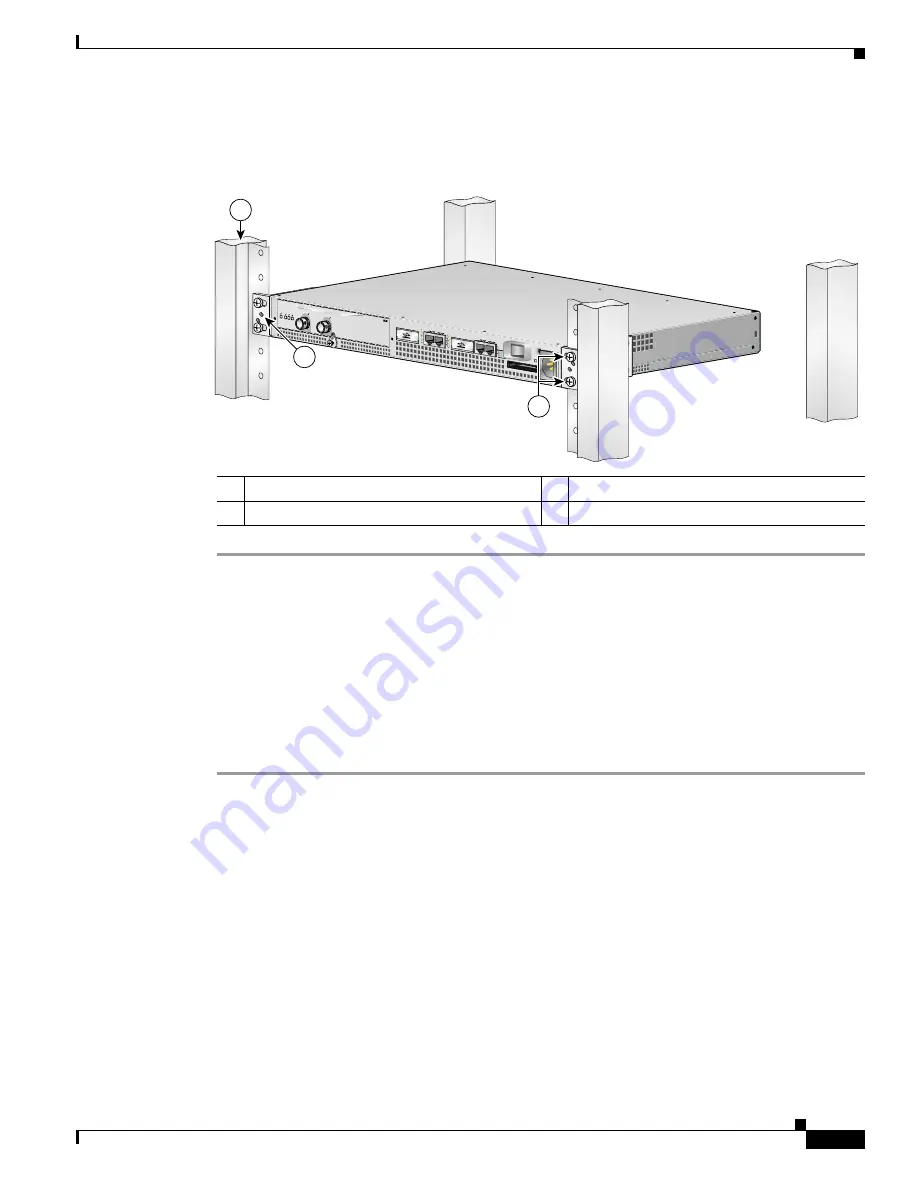
Figure 2-7
Installing the Cisco 7401ASR Router in a Four-Post Rack
Step 1
Make sure that the port adapter latch is in the locked position and the screw is tightened.
Step 2
Make sure the rack brakes are locked or the rack is stabilized.
Step 3
Position the router so the front is closest to you and lift it carefully into the rack. To prevent injury, avoid
any sudden twists or moves.
Step 4
Slide the chassis into the rack, pushing it back until the brackets meet the mounting strips or posts on
both sides of the rack.
Step 5
Keeping the brackets flush against the posts or mounting strips, align the holes in the brackets with the
holes on the rack or mounting strip.
Step 6
For each bracket, insert and tighten two 12-24 x 0.5-inch screws to the rack.
This completes the procedure for installing the chassis in the rack. Proceed to the
“Attaching a Chassis
Ground Connection” section on page 2-11
to continue the installation.
Attaching a Chassis Ground Connection
Before you connect power or turn on power to your router, we strongly recommend that you provide an
adequate chassis ground (earth) connection for the router chassis. Chassis grounding connectors are
provided on each Cisco 7401ASR router chassis. (See
Figure 2-8 on page 2-12
.)
To ensure the chassis grounding connection that you provide is adequate, you will need the following
parts and tools:
1
Four-post rack
3
Four 12-24 x 0.5-inch screws
2
Screw hole for the cable-management bracket
EN
AB
LE
D
RX CELLSRX CARRIER
RX ALARM
TX
RX
ENHANCED ATM
50534
1
2
3


