


2-17
Cisco 6160 Hardware Installation Guide
OL-2190-02 B0
Chapter 2 Preparing for Installation
Required Tools and Equipment
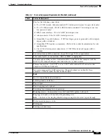
Wire for the following connections:
•
T1 or T1 IMA trunk—Industry standard T1 twisted-pair wire (use two-pair stock only).
•
T1 or T1 IMA subtend—RJ-48 to RJ-48 industry standard T1 twisted-pair wire (use
two-pair stock only).
•
BITS
4
clock interface—24 to 26 AWG
5
twisted-pair wire.
•
Alarm contacts—24 to 26 AWG twisted-pair wire.
•
Ground the Cisco 6160 chassis—8 AWG or larger, green or green and yellow striped,
copper solid or stranded.
•
Ground the POTS splitter, as necessary—Refer to the vendor documentation for wire
specifications.
•
Cisco 6160 chassis power connections—12 AWG black and red copper solid or
stranded.
Coaxial cable for a DS3 connection—Type 734A, type 735A, or equivalent.
Fiber cable for OC-3c connections—SMF or MMF, as appropriate.
7Console and auxiliary cables—Unshielded RJ-45 serial cable that complies with the
EIA/TIA-232 standard and provides connection to a system console.
Ethernet connection—Cat 5 UTP
6
or Cat 5 STP
7
cable with an RJ-45 connector that
complies with Ethernet standards.
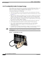
Necessary equipment for ESD protection—Required whenever you handle Cisco
equipment, which includes the chassis and modules.
Tools
No 1 3/16-inch flat-head screwdriver.
A Phillips-head screwdriver.
Wire stripper.
Wire-wrapping tool, optional.
Grounding lug crimping tool, as necessary.
Mounting screws—To mount the Cisco 6160 and POTS splitter to the rack.
Ring lugs (5/8-inch or 3/4-inch) for the grounding wire.
Note
The hole in the ring lug should be large enough for the screw to pass through.
Metric measuring tape or ruler.
Marking pen.
Tie wraps, as necessary.
Table 2-4
Tool and Equipment Requirements Checklist (continued)
Check
Tools and Equipment