background image

26

Cisco 6130 NI-1 to NI-2 Upgrade Kit Conversion Procedures

78-10709-03

Cisco 6130 NI-1 to NI-2 Conversion Procedures

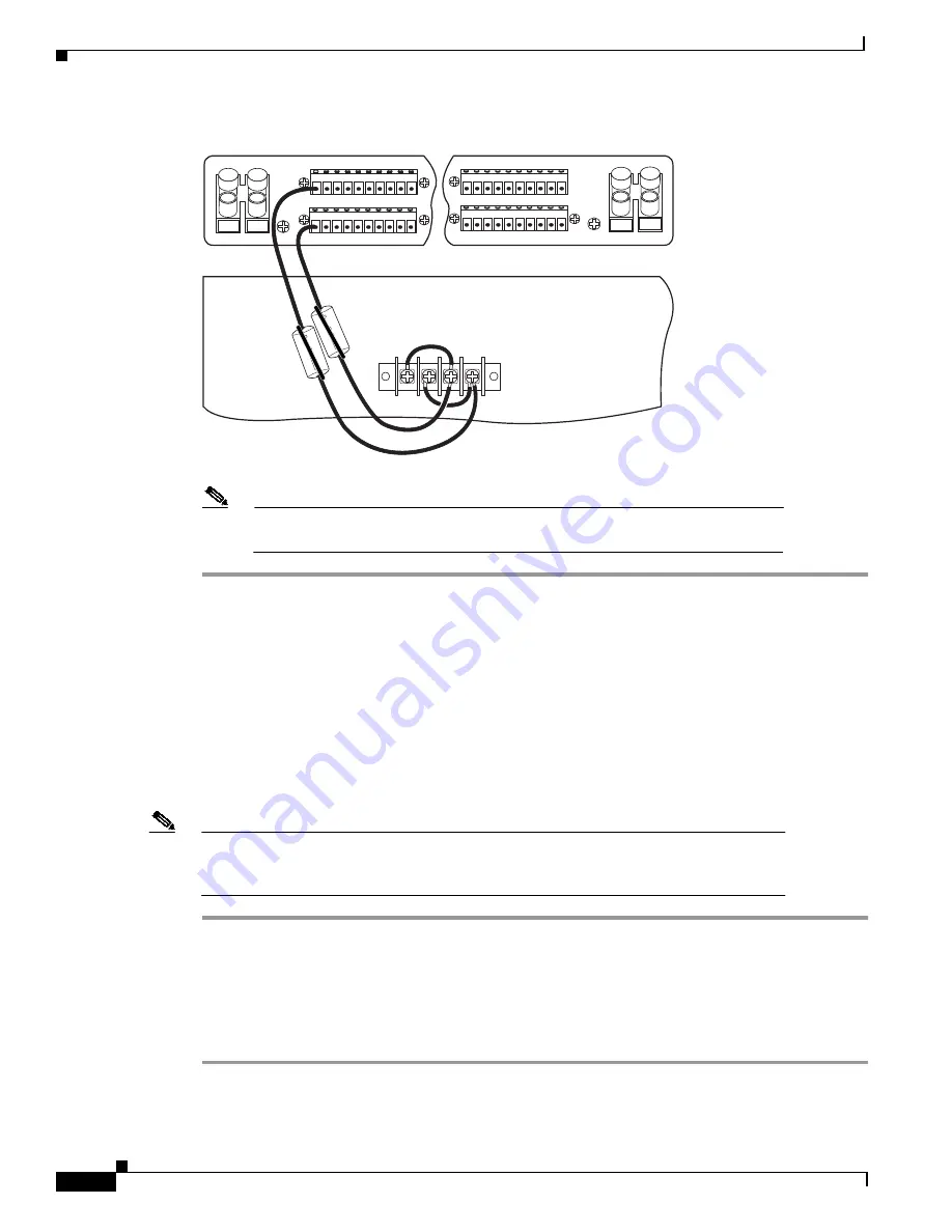
Figure 7

Power Connections for the Cisco 6130—Single-Power Feed

Note

Figure 6 and Figure 7 show the wires looped through a ferrite. If you use thicker
wire, it will not be necessary to loop the wire through the ferrite.

Disconnect the Cisco 6130 Cables

Disconnect the Champ cables from the J39 and J42 connectors on the chassis backplane. Do not
disconnect any of the other cables at this time.

Remove the Cisco 6130 Chassis Ground

If you have 14 AWG copper wire connecting the Cisco 6130 chassis ground, complete the following
steps to disconnect the Cisco 6130 chassis ground connection:

Note

If you do not have 12 AWG wire installed, it will be necessary to completely remove the
grounding wire. You will replace the grounding wire with a larger gauge wire later in
the procedures.

Step 1

Use a 3/16-inch flat-head screwdriver to loosen the screw on the rack.

Step 2

Unhook the end of the copper wire that is around the screw on the rack.

Step 3

Loosen the compression screw that is provided on the grounding lug of the Cisco 6130.

Step 4

Remove the other end of the wire.

Step 5

Tighten the compression screw.

1 2 3 4 5 6 7 8 9 10

Cisco 6130

P13

-48V_A

-48RTN

-48V_B

-48RTN

NEG

NEG

POS

POS

NEG DC

NEG DC

POS RTN

POS RTN

B

A

1 2 3 4 5 6 7 8 9 10

1 2 3 4 5 6 7 8 9 10

1 2 3 4 5 6 7 8 9 10

18394

Summary of Contents for 6130 NI-1

Page 1: ...th network interface 2 NI 2 card system Note Currently the Cisco 6130 with NI 2 system only supports quad port DMT 2 ATU C 4xDMT 2 quad port flexi ATU C 4xflexi and quad port STU C 4xSDSL line cards Contents These release notes describe the following topics Conversion Prerequisites page 2 Required Tools and Equipment page 2 Safety Requirements page 3 Subtended Network Configuration Overview page 9...

Page 2: ...he power connections cables Thermal shield Required Tools and Equipment Table 1 lists the tools and equipment that are required to convert from a Cisco 6130 with NI 1 card system to a Cisco 6130 with NI 2 card system Table 1 Tool and Equipment Requirements Checklist Check Tools and Equipment Hardware Components Cisco 6100 NI 1 to NI 2 Upgrade Kit System I O card for NI 2 system Plastic ESD shield ...

Page 3: ...stallation Note To see translations of the warnings that appear in this publication refer to the Regulatory Compliance and Safety Information for the Cisco 6100 Series System document that accompanied this product Tips In the following warnings the terms cover panel and safety cover refer to the Cisco 6100 6130 chassis front cover Backplane screws Included on the backplane Wire wrapping tool Wire ...

Page 4: ... the backplane circuitry does not become damaged Caution Installing the line cards in the chassis with the power leads reversed can damage the line cards Caution If fuses are already installed in the fuse and alarm panel remove them You can replace the fuses after the system is installed Do not power up the system while you install and connect the system Caution If the power connections are improp...

Page 5: ...lizers before mounting or servicing the unit in the rack Warning Class 1 laser product Warning Because invisible laser radiation may be emitted from the aperture of the OC 3 NI 2 card optical interface port when no optical cable is connected avoid exposure to laser radiation and do not stare into an open aperture Warning Use copper conductors only Warning A readily accessible two poled disconnect ...

Page 6: ...t Warning This equipment is intended to be grounded Ensure that the host is connected to earth ground during normal use Warning This equipment needs to be grounded Use a green and yellow 12 to 14 American Wire Gauge AWG ground wire to connect the host to earth ground during normal use Warning Incorrect connection of this or connected equipment to a general purpose outlet could result in a hazardou...

Page 7: ...avoid disturbing field wiring connections Warning The power supply circuitry for the equipment can constitute an energy hazard Before you install or replace the equipment remove all jewelry including rings necklaces and watches Metal objects can come into contact with exposed power supply wiring or circuitry inside the DSLAM equipment This could cause the metal objects to heat up and cause serious...

Page 8: ...een disconnected at the network interface Warning This is a Class A product based on the standard of the Voluntary Control Council for Interference by Information Technology Equipment VCCI If this equipment is used in a domestic environment radio disturbance may arise When such trouble occurs the user may be required to take corrective actions Warning Do not use this product near water for example...

Page 9: ...operly with the card Do not force the line card into its slot This action can damage the pins on the backplane if they are not aligned properly with the line card Ensure that the system I O card is straight and parallel to the chassis backplane when you install the card onto the connectors The pins on the connectors can be damaged if the card is not installed correctly Ensure that the card is stra...

Page 10: ...nk port that operates as fast as any subtended link The NI 2 card provides three types of subtended network connections A high speed OC 3 optical ATM interface that supports single mode fiber SMF intermediate range A high speed OC 3 optical ATM interface that supports multimode fiber MMF short range A DS3 ATM interface The following sections detail the three types of subtending network connections...

Page 11: ...eme is not optimal for data throughput for daisy chained Cisco 6130 chassis that use DS3 NI 2 cards Cisco IOS software is not implemented to manage the primary Cisco 6130 chassis and all subtended Cisco 6130 chassis as a single large Cisco 6130 with NI 2 card system The initial release of Cisco 6130 with NI 2 system emphasizes bandwidth aggregation Each Cisco 6130 supports an independent IOS proce...

Page 12: ...ng your system from a Cisco 6130 with NI 1 system to a Cisco 6130 with NI 2 system Warning Only trained and qualified personnel should be allowed to install replace or service this equipment Note Before installing and cabling the equipment be aware of standard safety practices and the hazards involved in working with electrical circuitry to prevent accidents See the Safety Requirements section on ...

Page 13: ...sco 6130 system node software to Release 3 0 0 3 Run the NI 1 to NI 2 conversion utility 4 Run the NI 2 preparation build 5 Remove the power from the system 6 Remove the current system I O card 7 Remove the current DS3 subtending I O card if applicable 8 Remove the alarm contact wires 9 Disconnect the Cisco 6130 power connections 10 Disconnect the Cisco 6130 cables 11 Remove the Cisco 6130 chassis...

Page 14: ...If your system is already running Release 3 0 0 or Release 3 1 0 code proceed to the Run the NI 1 to NI 2 Conversion Utility section on page 15 Caution The procedure that is outlined in the following steps will force the Cisco 6130 system to stop providing DSL service for the duration of the conversion procedures Do not proceed unless this is acceptable 28 Connect the NI 2 card to the network 29 R...

Page 15: ...methods Go to http www cisco com cgi bin tablebuild pl looprunner and download Release 3 0 0 to your computer Go to www cisco com and log in Select Software Center Access Software 6100 Series Download either the c6100 3 0 exe file or the c6100 3 0 tar file Step 3 Upgrade the Cisco 6130 system node software to Release 3 0 0 Note During the software upgrade the STATUS LEDs on the xTU C and system co...

Page 16: ...de You have saved the NSS file in ViewRunner for Windows or ViewRunner for HP OpenView 3 0 The node software is version 2 2 1 to 3 0 Downloading the Utility Packages from the Cisco Web Site To access the utility packages on the Cisco web site CCO complete the following steps Step 1 Access CCO in one of the following ways WWW www cisco com Telnet cco cisco com Modem using standard connection rates ...

Page 17: ...he utility defaults to v NI2defaults f FCM with path SCFeature Compatibility Matrix file If you do not enter a filename the utility defaults to f FCM See the NI 1 to NI 2 Migration Utility Input Examples section on page 17 for some examples of using these command options Note If you do not specify a path the utility assumes the path is the same as the NSS file path NI 1 to NI 2 Migration Utility I...

Page 18: ...liminate the risk of ESD damage to the equipment Cards are subject to ESD damage whenever they are removed from the chassis Step 1 Insert the Cisco NI 1 to NI 2 Line Card Upgrade Utility CD The CD contains the 3 0 0 A rdf file along with images for the system controller card 4xflexi line cards and the 4xSDSL line cards Step 2 Copy the rdf and image files to the appropriate Windows or UNIX director...

Page 19: ...chassis may now be used to upgrade additional 4xflexi or 4xSDSL line cards from other NI 1 systems that are currently being converted to NI 2 systems To program the line card s boot ROM insert the line cards into the chassis and the new image will download Step 5 Remove the system controller card 4xflexi line cards and 4xSDSL line cards from the chassis a Lift up the ejector tab s This action disc...

Page 20: ... field With the earlier version prior to Release 2 4 0 the DS3 BNC connectors are located at the bottom left corner of the card and the 10BaseT Ethernet LAN connector is located across the bottom of the card The removal procedures are the same for each version of the system I O card Step 1 Remove the optional rear cover if your system has one Step 2 Use a Phillips head screwdriver to remove the tw...

Page 21: ...he DS3 NI 1 card from the network if you have a DS3 NI 1 card installed in slot 10 of the Cisco 6130 chassis a Disconnect the end of the cable that attaches to the receive J4 DS3 BNC connector on the system I O card on the chassis backplane b Disconnect the end of the cable that attaches to the transmit J3 DS3 BNC connector on the system I O card on the chassis backplane J39 28908 J48 J45 P13 P3 J...

Page 22: ... quarter inch socket driver or wrench to remove the two standoff screws from the system I O card on the Cisco 6130 backplane Keep the standoff screws for future use Remove the Current DS3 Subtending I O Card Caution Proper ESD protection is required whenever you handle Cisco DSLAM equipment Installation and maintenance personnel should be properly grounded using ground straps to eliminate the risk...

Page 23: ...h to remove the two additional standoff screws that hold the DS3 subtending I O card in place Keep the standoff screws for future use Step 4 Lift and disconnect the DS3 subtending I O card from connector J48 a 96 pin Deutsche Industrie Norm DIN connector on the subtending host chassis backplane Step 5 Use a one quarter inch socket driver or wrench to remove the two standoff screws from the DS3 sub...

Page 24: ...ve a fan tray installed Figure 5 shows how the fan tray two position header P2 connects to the fan tray alarm contacts P14 pins 7 and 8 on the Cisco 6130 backplane Figure 5 Wiring the Fan Tray Alarm Contacts Step 3 Disconnect any additional alarm contacts as necessary Cisco 6100 32211 P2 J1 Fan tray FAN P2 J1 48VA RTN 48VB RTN 1 2 1 2 P14 P17 P15 E2A VISUAL AUDIBLE FAN ALARM MIN MAJ CRIT ACO MIN M...

Page 25: ...e these wires with a larger gauge wire later in the procedures Step 1 Use a socket driver or a Phillips head screwdriver to remove the clear cover over the Cisco 6130 power connections Step 2 Disconnect the wires connecting the Cisco 6130 chassis to the fuse and alarm panel POS RTN and NEG DC connections as shown in Figure 6 dual power feed and Figure 7 single power feed Figure 6 Power Connections...

Page 26: ... 6130 chassis ground complete the following steps to disconnect the Cisco 6130 chassis ground connection Note If you do not have 12 AWG wire installed it will be necessary to completely remove the grounding wire You will replace the grounding wire with a larger gauge wire later in the procedures Step 1 Use a 3 16 inch flat head screwdriver to loosen the screw on the rack Step 2 Unhook the end of t...

Page 27: ...river to remove the 23 backplane screws shown in Figure 8 Keep the backplane screws for future use Figure 8 Backplane Screw Locations for Removing the Lexan Shield Step 2 Carefully remove the existing lexan shield 33607 P14 P17 P15 E2A VISUAL AUDIBLE FAN ALARM MIN MAJ CRIT ACO MIN MAJ CRIT ACO MIN MAJ CRIT RING TIP 48V_B 48RTN 48V_A P13 48RTN MODEM POOL A OUT J45 P3 P9 J39 J42 MODEM POOL B OUT J46...

Page 28: ...hat will need to be reattached over the new lexan shield See Figure 9 for an illustration of the cut corner Figure 9 UL Label Installation Step 4 Place the new lexan shield over the backplane 33949 P14 P17 P15 E2A VISUAL AUDIBLE FAN ALARM MIN MAJ CRIT ACO MIN MAJ CRIT ACO MIN MAJ CRIT P13 48RTN J42 Backplane screw Standoff screw Backplane screw Old multiplexer shield Old multiplexer shield New mul...

Page 29: ...g the one quarter inch socket driver or wrench Ground the Cisco 6130 Chassis Complete the following steps to connect the grounding lug on the Cisco 6130 chassis directly to the rack Step 1 Verify that all paint or oxidation is removed from the rack at the point of the grounding connection Step 2 Measure enough wire 12 AWG or thicker green or green with yellow stripes stranded copper wire to connec...

Page 30: ... compression screw Step 9 Tighten the compression screw over the copper wire Note Do not ground the components in a rack by chaining them together The left side of Figure 11 shows how to ground the Cisco 6130 chassis Figure 11 Grounding the Cisco 6130 Chassis Connect the Cisco 6130 to the Cisco 6120 Connect the one to two Champ cables from the Cisco 6100 connectors J39 through J44 to the Cisco 612...

Page 31: ...g xTU C line cards refer to the Cisco 6130 with NI 2 Hardware Installation Guide for cable part numbers and cabling diagrams 1st Cisco 6120 Cisco 6100 6130 27319 P14 P17 P15 E2A VISUAL AUDIBLE FAN ALARM MIN MAJ CRIT ACO MIN MAJ CRIT ACO MIN MAJ CRIT ANALOG TEST I F RING TIP P18 48V_B 48RTN 48V_A 48RTN P13 MODEM POOL A OUT J45 J48 P3 P9 J39 J42 MODEM POOL B OUT J46 J43 J44 J41 J40 J47 J49 P2 J3 J4 ...

Page 32: ...Connect each Cisco 6130 with NI 2 system component to a separate fuse Do not power the components in the rack by chaining them together Step 1 Reconnect the wires that connect the Cisco 6130 chassis to the fuse and alarm panel POS RTN and NEG DC connections as shown in Figure 6 dual power feed and Figure 7 single power feed These wires were removed in the Disconnect the Cisco 6130 Power Connection...

Page 33: ...gure 13 Tighten the standoff screws using the one quarter inch socket driver or wrench Caution Be careful when you remove the standoff screws and reinsert the screws into the screw holes on the backplane so that the backplane circuitry does not become damaged Figure 13 Standoff Screw Locations for the System I O Card Installation 42677 P14 P17 P15 E2A VISUAL AUDIBLE FAN ALARM MIN MAJ CRIT ACO MIN ...

Page 34: ...e 14 Figure 14 System I O Card Installation Step 3 Carefully press the system I O card onto the Cisco 6130 connectors P3 and P9 on the chassis backplane until the system I O card is in place and against the standoff screws Step 4 Use a Phillips head screwdriver and four backplane screws to attach the system I O card to the standoff screws as shown in Figure 14 J39 28071 J48 J45 P13 P9 P3 J47 J49 J...

Page 35: ...Installation Step 6 Attach the EMI cover on the EMI fence as shown in Figure 15 Caution Be careful not to bend the tabs on the EMI cover when you install the cover on the EMI fence Step 7 Verify that no EMI cover tabs are outside the EMI fence Step 8 Use a Phillip head screwdriver and a screw to attach the EMI cover to the EMI cover bracket as shown in Figure 15 J39 30749 J48 J45 P13 P14 P17 P15 S...

Page 36: ...p 10 Use a one quarter inch socket driver or wrench to screw a standoff screw between relays K4 and K5 as shown in Figure 16 Tighten the standoff screws using the one quarter inch socket driver or wrench Step 11 Place the ESD shield above the standoff screw that you installed in Step 10 so that the hole in the shield aligns with the standoff screw as shown in Figure 16 Step 12 Use a Phillips head ...

Page 37: ...s Visual critical Visual major Visual minor Audible critical Audible major Audible minor Power module alarms Remote alarm cutoff Reserved several pins that are reserved for future specification One NI 2 card in the Cisco 6130 chassis manages the alarms that are generated by the wire wrap pins P1 through P5 An alarm cutoff ACO switch located on the NI 2 card faceplate shuts off the audible alarms C...

Page 38: ...er P5 Pin 1 left AUD2 _CRIT3 _CO4 2 AUD audible 3 CRIT critical 4 CO common AUD_MIN5 _CO 5 MIN minimum VIS6 _MAJ_CO 6 VIS visual FAN ALARM RX_BITS7 _TIPA 7 RX_BITS receive building integrated timing source Pin 2 AUD_CRIT_NO8 8 NO normally open AUD_MIN_NO VIS_MAJ9 _NO 9 MAJ major Reserved RX_BITS_RINGA Pin 3 AUD_CRIT_NC10 10 NC normally closed AUD_MIN_NC VIS_MAJ_NC Reserved RX_BITS_GND GND Pin 4 AU...

Page 39: ...of the system controller card This action disconnects the card from the backplane Step 2 Carefully slide the card out of the slot Remove the NI 1 Card This section provides the removal procedures for the DS3 and the OC 3c NI 1 cards Removing a DS3 NI 1 Card Caution Proper ESD protection is required whenever you handle Cisco DSLAM equipment Installation and maintenance personnel should be properly ...

Page 40: ... the transmit and receive connectors in the inset on the front panel of the OC 3c NI 1 card See Figure 19 for the OC 3c NI 1 connection location Figure 19 OC 3c NI 1 Connection Warning Because invisible laser radiation may be emitted from the aperture of the OC 3 NI 2 card optical interface port when no optical cable is connected avoid exposure to laser radiation and do not stare into an open aper...

Page 41: ... page 19 Turn on the breakers in the fuse and alarm panel Table 5 Fuse Calculation for the Cisco 6130 with NI 2 System Components Component Instructions Calculation Cisco 6130 Chassis1 2 1 For a Direct Connect configuration the maximum number of Cisco 6130 chassis is two per rack 2 Complete this section for each subtending host 1a If you are using 4xDMT 2 line cards multiply 16 5W by the total num...

Page 42: ...If the LED is Green The fan is operational Not green The fan is not operational and the fan tray is in alarm mode Refer to the Cisco 6130 with NI 2 Hardware Installation Guide for corrective action Caution It is important that the Cisco 6130 cooling fans run continuously Warning The power supply circuitry for the Cisco DSLAM equipment can constitute an energy hazard Before you install or replace t...

Page 43: ...n the faceplate of each card is required for the card to be fully seated Complete the following steps to install the NI 2 card in the Cisco 6130 It is important that you accomplish each step completely before moving on to the next step Step 1 Inspect the NI 2 card Verify that the daughterboard is fully seated on the main board Step 2 Verify that slots 10 and 11 of the Cisco 6130 have no bent pins ...

Page 44: ...t Step 3 Push on the faceplate to fully seat the blank faceplate Step 4 Press down on the ejector tab to secure the faceplate Step 5 Repeat Step 1 through Step 4 for the system controller card in slot 12 Install the xTU C Line Cards Caution Proper ESD protection is required each time you handle Cisco DSLAM equipment Installation and maintenance personnel should be properly grounded using ground st...

Page 45: ...ejector tab to secure the line card and connect it to the backplane Step 5 Lock the xTU C line cards as necessary Note It is not necessary to lock the xTU C line cards Use a flat head screwdriver to turn the locking tab so that it overlaps the xTU C line card to prevent inadvertent dislodging as shown in Figure 21 Figure 21 Locking the xTU C Line Card Step 6 Install the remaining xTU C line cards ...

Page 46: ...S3 NI 2 card connections are on the system I O card which is located on the backplane of the Cisco 6130 chassis These connections attach to the ATM switch Two 75 ohm DS3 Bayonet Neill Concelman BNC connectors are provided for DS3 transmit J14 and receive J12 See Figure 22 for the location of the DS3 BNC connectors Figure 22 DS3 NI 2 Connection Locations Step 2 Attach one end of a coaxial cable typ...

Page 47: ...O card on the Cisco 6130 backplane Step 5 Attach the end of the cable that you used in Step 4 which originates at the receive DS3 BNC connector to the ATM switch OC 3 Network Connection Installation Complete the following steps to connect the OC 3 NI 2 card to the network Warning Do not stare into the beam or view it directly with optical instruments Step 1 Verify that the OC 3 NI 2 card is in slo...

Page 48: ...e The connector IDs are silkscreened inside the inset Step 4 Attach the transmit optical fiber to the receive connector in the inset on the faceplate of the OC 3 NI 2 card trunk 1 interface connector RX See Figure 23 for the OC 3 network interface connection location Step 5 Allow enough slack in the cable so that the fan tray can be opened and the fans can be maintained Step 6 Coil the fiber loose...

Page 49: ...cables are not provided by Cisco Systems Inc Complete the following steps to cable the system I O card for subtending Step 1 On the subtending host chassis backplane attach one end of a BNC cable to the transmit DS3 BNC connector TX1 on the system I O card Step 2 On the subtended chassis backplane attach the end of the BNC cable used in Step 1 to the receive DS3 BNC connector RX on the system I O ...

Page 50: ... NI 2 system for OC 3 subtending complete the following steps Step 1 Locate the trunk transmit top and receive ports on the front of the OC 3 NI 2 card Step 2 Connect the OC 3 fiber optic cable from the subtending host chassis transmit port on the OC 3 NI 2 card to the receive port on the subtended node chassis OC 3 NI 2 card P1 P2 P3 P5 P4 Subtending host chassis system I O card Trunk 1 Receive T...

Page 51: ...R MINOR POWER STATUS ACTIVE FAN 1 FAN 2 ALARMS C N S L A U X E N E T ACO RESET S T A T T X T E S T R C L K S T A T R X S T A T T X T E S T R C L K S T A T R X TRNK 1 SBTD 2 ATU C 1 ACTIVE STATUS ATU C 2 ATU C 3 ATU C 4 ATU C 1 ACTIVE STATUS ATU C 2 ATU C 3 ATU C 4 1st subtended chassis Cisco 6130 ATU C 1 ACTIVE STATUS ATU C 2 ATU C 3 ATU C 4 ATU C 1 ACTIVE STATUS ATU C 2 ATU C 3 ATU C 4 ATU C 1 AC...

Page 52: ...ct a Console Terminal Connect a VT100 compatible terminal to the system console port on the NI 2 card CNSL Connect the terminal to a power source and set it up using the values that are shown in Table 7 Warning The ports labeled ENET CNSL and AUX are SELV circuits SELV circuits should be connected only to other SELV circuits Because the DSL circuits are treated like telephone network voltage avoid...

Page 53: ...0 with NI 2 system DSLAM enable Password enter your password DSLAM configure terminal DSLAM config service internal DSLAM config exit DSLAM ni2 upgrade DSLAM configure terminal DSLAM config no service internal DSLAM config exit DSLAM Load the Subscriber Information into the NI 2 Card After the utility successfully completes you need to use FTP to transfer the files from the computer on which you r...

Page 54: ...he New Front Cover The front cover on the existing Cisco 6130 with NI 1 chassis is not deep enough to accommodate the NI 2 card Consequently the existing front cover must be replaced with the new deeper front cover Complete the following steps to replace the existing front cover with a new front cover Step 1 Lift out and up on the existing front cover to remove it from the chassis Step 2 Hold the ...

Page 55: ... the Rear Cover with the Latches Step 2 Release the latches after the rear cover is in place 26875 P14 P17 P15 E2A VISUAL AUDIBLE FAN ALARM MIN MAJ CRIT ACO MIN MAJ CRIT ACO MIN MAJ CRIT ANALOG TEST I F RING TIP P18 48V_B 48RTN 48V_A 48RTN P13 MODEM POOL A OUT J45 J48 P3 P9 J39 J42 MODEM POOL B OUT J46 J43 J44 J41 J40 J47 J49 Latch Latch ...

Page 56: ... Migration Utility Note for the procedures necessary to convert subscribers from the ViewRunner management software to CDM Related Documentation A complete list of all DSL product related documentation is available on the World Wide Web at http www cisco com univercd cc td doc product dsl_prod index htm 26389 P17 P15 E2A VISUAL AUDIBLE FAN ALARM MIN MAJ CRIT ACO MIN MAJ CRIT ACO MIN MAJ CRIT ANALO...

Page 57: ...800 553 NETS 6387 Obtaining Technical Assistance Cisco provides Cisco Connection Online CCO as a starting point for all technical assistance Warranty or maintenance contract customers can use the Technical Assistance Center All customers can submit technical feedback on Cisco documentation using the web e mail a self addressed stamped response card included in many printed docs or by sending mail ...

Page 58: ...al assistance with a Cisco product that is under warranty or covered by a maintenance contract To display the TAC web site that includes links to technical support information and software upgrades and for requesting TAC support use www cisco com techsupport To contact by e mail use one of the following In North America TAC can be reached at 800 553 2447 or 408 526 7209 For other telephone numbers...

Page 59: ...tise IQ FastTrack IQ Readiness Scorecard The IQ Logo Kernel Proxy MGX Natural Network Viewer NetSonar Network Registrar the Networkers logo Packet PIX Point and Click Internetworking Policy Builder Precept RateMUX ReyMaster ReyView ScriptShare Secure Script Shop with Me SlideCast SMARTnet SVX The Cell TrafficDirector TransPath VlanDirector Voice LAN Wavelength Router Workgroup Director and Workgro...

Page 60: ...60 Cisco 6130 NI 1 to NI 2 Upgrade Kit Conversion Procedures 78 10709 03 Obtaining Technical Assistance ...

Reviews: