Troubleshooting the Router A-5
Reading the LEDs
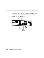
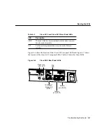
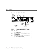
Figure A-3
Cisco 2611 Rear-Panel LEDs
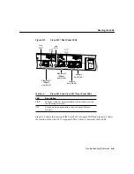
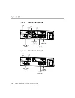
Figure A-4 shows the location of the Cisco 2612 rear-panel LEDs and Figure A-5 shows
the location of the Cisco 2613 rear-panel LEDs. Table A-3 describes these LEDs.
Table A-2
Cisco 2610 and Cisco 2611 Rear-Panel LEDs
LED
Description
LINK
When on, a link has been established with the hub or switch at
the other end of the cable.
ACT
Packets are being transmitted or received on the Ethernet
interface.
H11584
SEE MANUAL BEFORE INSTALLATION
SERIAL 1
SERIAL 0
CONN
CONN
WIC
2A/S
SEE MANUAL BEFORE INSTALLATION
SERIAL 1
SERIAL 0
CONN
WIC
2A/S
Cisco 2611
W0
AUX
CONSOLE
ETHERNET 0/0 ACT
LINK
ACT
ETHERNET 0/1
LINK
Ethernet 0/0
10BaseT
port (RJ-45)
Ethernet 0/1
10BaseT
port (RJ-45)
Auxiliary
port (RJ-45)
Console
port (RJ-45)
Link
LED
ACT
LED
Link
LED
ACT
LED


