Maintaining the Router B-11
Closing the Chassis
Step 9
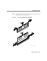
Insert the new SIMM by sliding the end with the metal fingers into the SIMM
connector socket at approximately a 90º angle to the system card. Gently rock
the SIMM back into place until the latches on both sides snap into place. Do not
use excessive force because the connector might break.
Step 10
Replace the router cover following the procedure in the following section.
Step 11
Refer to the “Procedures for Recovering Boot and System Images” section on
page C-9 for instructions on how to place the Cisco IOS image on the
new SIMM.
Closing the Chassis
This section describes the procedure for closing the chassis by replacing the cover.
Replacing the Cover
Take the following steps to replace the cover:
Step 1
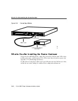
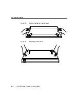
Position the two chassis sections, as shown in Figure B-2.
Step 2
Referring to Figure B-2, press the two chassis sections together and ensure the
following:
•
The top section fits into the rear of the bottom section. The bottom section
fits into the front of the top section.
•
Each side of the top and bottom sections fits together.
Step 3
When the two sections fit together snugly, slide the chassis top so until it fits into
the front bezel.
Step 4
Replace the cover screws. Tighten the screws to no more than 8 or 9 inch/pound
of torque.
Caution
To fit the two sections together, it might be necessary to work them together at
one end and then the other, working back and forth; however, use care to prevent bending
the chassis edges.

