Cisco MERAKI Catalyst CW9164 Installation Manual Download Page 21

Preferred Scanning Channels

The 6 GHz frequency band introduces 59 20 MHz channels. Due to a large number of channels, the standard implements a new efficient process for clients to
discover nearby access points. This is called Preferred Scanning Channels (PSC). PSCs are a set of 20-MHz channels that are spaced every 80 MHz. In order
to support the PSC-based clients and effectively onboard the clients in the least possible time, the 6 GHz channel selection in the RF profile for CW9164 Auto
RF configuration will be restricted to a set of PSC capable channels.

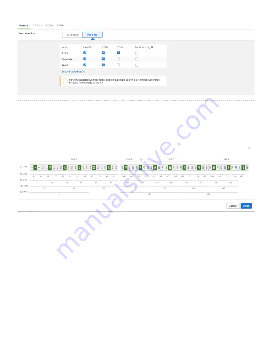
The list of the PSC channels is indicated above in green. Auto RF will choose a channel that is a PSC-supported channel for 20, 40, 80, and 160 MHz
frequencies.

Note

: When disabling a channel that is being used by Auto Channel configuration settings, the system will make sure to disable all 80 MHz of the closest PSC

channel.

Warning:

Please make sure to assign a PSC-supported channel when allocating a channel manually. There could be a substantial delay in the client connecting

to the Access Point if a non-PSC supported channel is selected during manual allocation

WPA3 Support

WiFi 6E in the 6 GHz frequency band requires the clients to support WPA3 as a mandatory mode of operation. WPA2-WPA3 transition mode is not supported in
the 6 GHz frequency. If an SSID is configured to operate across all three frequency bands, then the SSID should be configured to be WPA3 only

Note:

If an SSID is configured to support WPA3 transition mode across all three frequency bands, then the 2.4 GHz and the 5 GHz frequency will broadcast the

SSID with transition mode support. The SSID will not be broadcasted in the 6 GHz mode

21

Summary of Contents for Catalyst CW9164

Page 1: ...has a USB port About this Guide This guide provides instructions on how to install and configure your CW9164 access points This guide also provides mounting instructions and limited troubleshooting pr...

Page 2: ...158 F 20 C to 70 C Humidity 10 to 90 non condensing Physical Security Kensington lock hardpoint Screws that can be attached to the security hasp of the universal mounting bracket Concealed mount plat...

Page 3: ...3...

Page 4: ...ctive cover C Kensington lock hard point D Rubber Feet universal mounting bracket slide in points E Cable access bay The Meraki AP comes with the default Cisco universal mounting bracket AIR AP BRACKE...

Page 5: ...ing bracket has a security hasp and can be used to secure the access point to the universal mounting bracket Engaging the security screw prevents accidental dislodging and theft 2 Kensington lock The...

Page 6: ...ted operation of the AP Port0 2 4GHz 5GHz 6GHz Scan IoT USB AT 4x4 4x4 4x4 ON ON OFF BT 4x4 4x4 4x4 ON ON ON CW9164 AP can be powered by PoE power in different modes as mentioned above when using a Po...

Page 7: ...e the Conducting Site Surveys with MR Access Points for more details The CW9164 access point may be operated in the Run Dark mode for additional security and to reduce the visibility of the access poi...

Page 8: ...Cisco Universal Mount Bracket AIR AP BRACKET 2 8...

Page 9: ...T Rail mount attachment AIR AP T RAIL R and screws 5 Nos 6 32 x 1 4 included 9...

Page 10: ...familiar with standard practices for preventing accidents Read the wall mounting instructions carefully before beginning installation Failure to use the correct hardware or to follow the correct proce...

Page 11: ...int the LED will turn solid green or blue You should allow at least a few minutes for the firmware upgrade to complete depending on the speed of your internet connection Check and Configure Upstream F...

Page 12: ...reservations IP addresses are reserved for the MAC addresses of the Meraki APs Please consult the documentation for the DHCP server to configure DHCP reservations Collect Tools You will need the foll...

Page 13: ...in an office filled with workspaces divided by mid height cubicle walls installing on the ceiling or high on a wall would be ideal 2 Power over Ethernet supports a maximum cable length of 300 ft 100...

Page 14: ...T Rail Mount attachment To mount your AP on a drop ceiling T rail AIR AP T RAIL R included use the included T Rail mount attachment The T Rail mount attachment can be used to mount to most 9 16 15 16...

Page 15: ...nding holes A B or C on the mounting bracket over the mounting holes on the ceiling grid clip 5 Hold the mounting bracket and insert a 6 32 x 1 4 in screw into each of the four corresponding holes A B...

Page 16: ...oles on the bracket 2 Use a 0 1360 in 3 4772 mm bit to drill a pilot hole at the mounting hole locations you marked 3 Locate the pilot holes and then insert a fastener not included into each mounting...

Page 17: ...The AP is not ready to be mounted on the wall 17...

Page 18: ...ng Power to the AP If mounting to an electrical junction box feed the Ethernet cable through the cable access hole in the universal mounting bracket If mounting to a wall or ceiling the Ethernet cable...

Page 19: ...oth be secured in several ways If the AP has been installed using the universal mounting bracket it should be secured via a security screw and or Kensington lock If the universal mounting bracket was...

Page 20: ...t s web browser Check network coverage Confirm that you have good signal strength throughout your coverage area You can use the signal strength meter on a laptop smartphone or another wireless device...

Page 21: ...a channel that is being used by Auto Channel configuration settings the system will make sure to disable all 80 MHz of the closest PSC channel Warning Please make sure to assign a PSC supported channe...

Page 22: ...e letter G Gateway on top of the AP symbol Check Ethernet Port Functionality by Connecting to the AP 1 Disable the Wireless adapter on your computer 2 Make sure the Ethernet adapter on your device is...

Page 23: ...munications However there is no guarantee that interference will not occur in a particular installation Additional warranty information can be found at https meraki cisco com support process warranty...

Page 24: ...For additional information on Meraki hardware and for other installation guides please refer to documentation meraki com 24...

Reviews: