background image

VCC-SXCL3R           


Rev.

 905-0046-00


©2016 CIS Corporation. All rights reserved. 

1.


Handling Precautions 


The  camera  must  not  be  used  for  any  nuclear  equipments  or  aerospace  equipments  with  which  mechanical  failure  or 

malfunction could result in serious bodily injury or loss of human life.    Our warranty does not apply to damages or defects 

caused by irregular and/or abnormal use of the product.     


Please observe all warnings and cautions stated below.     

Our warranty does not apply to damages or malfunctions caused by neglecting these precautions. 


Do not use


or store


the camera in the extremely dusty or humid places.   


Do not apply excessive force or static electricity that could damage the camera. 


Do not shoot direct images that are extremely bright (e.g., light source, sun, etc.), and when camera is not in use, put the 

lens cap on.   


Follow the instructions in Chapter 6, “External connector pin assignment” for connecting the camera.    Improper 

connection may cause damages not only to the camera but also to the connected devices. 


Confirm the mutual ground potential carefully before connecting the camera to monitors or


computers.    Any AC leaks 

from the connected devices may cause damages or destroy the camera. 


Do not apply excessive voltage. (Use only the specified voltage.)    Unstable or improper power supply voltage may cause 

damages or malfunction of the camera.


The voltage ripple of camera power DC +12V

±

10% shall be within 

±

50mV.    Improper power supply voltage may cause 

noises on the video signals.   


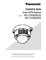
The rising time of camera power supply voltage shall be less than +10V, Max 60ms.    Please avoid noises like chattering 

when rising. 


10

40

20

30

50

10

11

12

[V

]

電源 電圧 立 ち 上 がり 時間

[ ms]

9

8

7

60

70


Voltage Rising Time 

ms


Power supply 
Voltage 

V


Summary of Contents for VCC-SXCL3R

Page 1: ...VCC SXCL3R Rev 905 0046 00 2016 CIS Corporation All rights reserved Camera Link I F SXGA Color Camera VCC SXCL3R Product Specifications Operational Manual CIS Corporation...

Page 2: ...5 2 Sub sampling and Frame Rate 11 6 External Connector Pin Assignment 12 6 1 6pins Circular Connector HR10 7R 6PA HIROSE 12 6 2 26pins Small Camera Link Connector 12226 1100 00 PL SUMITOMO 3M 12 7 T...

Page 3: ...ght source sun etc and when camera is not in use put the lens cap on Follow the instructions in Chapter 6 External connector pin assignment for connecting the camera Improper connection may cause dama...

Page 4: ...3M pixels 1 2 type CMOS sensor is utilized Features 29mm cubic in size Global shutter CMOS sensor Camera Link I F ROI Sub sampling External trigger 3 System Configuration 3 1 Camera Camera VCC SXCL3R...

Page 5: ...on 13 Weight Approx 50g 14 Lens mount C Mount Refer to overall dimension drawing 15 Optical axis accuracy Refer to drawing for CMOS Optical Axis Accuracy 16 Gain variable range x1 x32 image quality gu...

Page 6: ...put Photo Coupler 3 Trigger Input The minimum width of the trigger pulse Within 110 S 20mS Camera Link Input LVDS CC1 input Camera Link connector TTL input 6pins Circular connector Reference Trigger I...

Page 7: ...3R Rev 905 0046 00 2016 CIS Corporation All rights reserved 6 4 3 CMOS Spectral Response Please refer to the values for Red Green and Blue The lens characteristics and illuminant characteristics are e...

Page 8: ...nector Trig Negative polarity input 4 6pin Connector Trig Positive polarity input 5 6pin Connector Trig Negative polarity input Black level control values 7 0 15 Output black level 8bit Set value Fact...

Page 9: ...ion 1 Start operation Return to 0 after completion of operation ROI 50 0 1280 H 1024 V At 3Tap 1272 H 1024 V 1 1280 H 960 V At 3Tap 1272 H 960 V 2 1024 H 1024 V At 3Tap 1020 H 1024 V 3 1024 H 768 V At...

Page 10: ...H 1024 V 45 1990 x 10us 124 3 s 1024 H 768 V 54 1525 x 10us 124 3 s 800 H 600 V 40 1000 x 10us 124 1 s 640 H 480 V 36 710 x 10us 124 1 s Sub sampling mode 28 735 x 10us 79 7 s There is a jitter for 1...

Page 11: ...art below 636 H 480 V Refer to the chart below Sub sampling mode Refer to the chart below ROI Setting Manual shutter setting value Formula for Exposure Time 1272 H 1024 V 13 120 9 s 1272 H 960 V 22 18...

Page 12: ...l number 1024x768 1024x768 1020 768 Frame rate 64 3 fps 129 4 fps 242 6 fps Total CLK number for 1 Line 1355 CLK 668 CLK 351 CLK ROI 4 Pixel number 800x600 800x600 792 600 Frame rate 95 9 fps 191 8 fp...

Page 13: ...Trigger Input Isolated 6 GND GND for Pin 1 Camera Link Base Configuration PoCL non PoCL 12226 1100 00PL 3M Pin No Signal Name Description 1 26 Power IN or GND PoCL DC 12VPower Input non PoCL GND 13 1...

Page 14: ...8 1273 1275 1277 1279 1274 1276 1278 1280 1 2 Video Out 1 2 7 9 1 2 8 0 LVAL Out Effective Data 424 CLK 16 CLK DVAL Out 1H 440 CLK Camera Link Port B Camera Link Port A 1 4 7 10 2 5 8 11 414 417 420 4...

Page 15: ...er IDLE StreamPacket Image Header StreamPacket IDLE IDLE 7 2 Vertical Synchronous Timing FVAL Out 1Frame 1078H Effective Line 1024H DVAL Out LVAL Out Effective Line 1024 1024 1 1 Video Out Effective L...

Page 16: ...Time Delay Exposure Time Delay A TRIG IN Exposure Out Exposure Time Image Header IDLE StreamPacket Image Header StreamPacket IDLE IDLE 7 4 Pulse Width Trigger Shutter Mode The minimum pulse width 110...

Page 17: ...TRIGGER Exposure FVAL TRIGGER Exposure FVAL At trigger shutter mode please be carefully noted the reduction of exposure time when the next trigger is overlapped Please refer to the Section 5 Function...

Page 18: ...range 0x0000 0xFFFF With decimal notation Only 0 9 can be input Input range 0 65535 At initialization Prompt is indicated after command is processed Input command in capital letters following to the...

Page 19: ...h 2 4 2Tap 8bit Output CLK 72MHz 640 2Tap H x 1024 V Trigger shutter mode 3 0 Normal shutter mode Trigger shutter mode OFF Trigger input settings 4 0 Camera Link CC1 Positive polarity input Black leve...

Page 20: ...VCC SXCL3R Rev 905 0046 00 2016 CIS Corporation All rights reserved 19 10 CMOS Optical Axis Accuracy...

Page 21: ...VCC SXCL3R Rev 905 0046 00 2016 CIS Corporation All rights reserved 20 11 Dimensions...

Page 22: ...ormation contained in the instructions in this Product Specification and Operational Manual In case damages or losses are caused by repair or modification conducted by the customer or any unauthorized...

Reviews: