WM8940
82
Rev 4.4
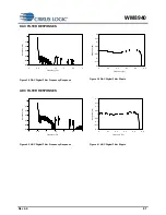
HIGHPASS FILTER
The WM8940 has a selectable digital high pass filter in the ADC filter path. This filter has two modes,
audio and applications. In audio mode the filter is a 1
st
order IIR with a cut-off of around 3.7Hz. In
applications mode the filter is a 2
nd
order high pass filter with a selectable cut-off frequency.
-40
-35
-30
-25
-20
-15
-10
-5
0
5
0
5
10
15
20
25
30
35
40
45
Frequency (Hz)
R
e
s
p
o
n
s
e
(
d
B
)
-60
-50
-40
-30
-20
-10
0
10
0
200
400
600
800
1000
1200
Frequency (Hz)
R
e
sp
o
n
se
(
d
B
)
Figure 42 ADC High pass Filter Response, HPFAPP=0
Figure 43 ADC High pass Filter Responses (48kHz),
HPFAPP=1, all cut-off settings shown.
-80
-70
-60
-50
-40
-30
-20
-10
0
10
0
200
400
600
800
1000
1200
Frequency (Hz)
R
e
s
p
o
n
s
e
(
d
B
)
-90
-80
-70
-60
-50
-40
-30
-20
-10
0
10
0
200
400
600
800
1000
1200
Frequency (Hz)
R
e
s
p
o
n
s
e
(
d
B
)
Figure 44 ADC High pass Filter Responses (24kHz),
HPFAPP=1, all cut-off settings shown.
Figure 45 ADC Highpass Filter Responses (12kHz),
HPFAPP=1, all cutoff settings shown.
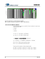
NOTCH FILTERS AND LOW-PASS FILTER
The WM8940 supports four programmable notch filters. The fourth notch filter can be configured as a
low pass filter. The following illustrates three digital notch filters, followed by a single low pass filter in
the ADC filter path. Both the centre frequency and -3dB bandwidth are programmable for the notch
filters. The cut off frequency is programmable for the low pass filter. The following graphs show the
responses of 1) a single notch filter at three chosen centre frequencies, with three bandwidths for
each, 2) the low pass filter at three chosen cut off frequencies and 3) the cascade of three notch filters
followed by the low pass filter, each with a different centre / cut off frequency with three bandwidths
for each.


