WM8940
Rev 4.4
21
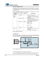
Output from
AUX amp
MICP
MICN
VMID
AUX2INPPGA
R44[2]
MICN2INPPGA
R44[1]
MICP2INPPGA
R44[0]
To input
BOOST/mix
stage
INPPGAVOL
R45[5:0]
Gain=-12 to +35.25dB
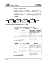
Figure 6 Microphone Input PGA Circuit (switch positions shown are for differential mic input)
REGISTER
ADDRESS
BIT
LABEL
DEFAULT
DESCRIPTION
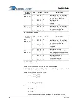
R44
Input Control
2
AUX2INPPGA
0
Select AUX amplifier output as input PGA
signal source.
0=AUX not connected to input PGA
1=AUX connected to input PGA amplifier
negative terminal.
1
MICN2INPPGA 1
Connect MICN to input PGA negative
terminal.
0=MICN not connected to input PGA
1=MICN connected to input PGA amplifier
negative terminal.
0
MICP2INPPGA 0
Connect input PGA amplifier positive
terminal to MICP or VMID.
0 = input PGA amplifier positive terminal
connected to VMID
1 = input PGA amplifier positive terminal
connected to MICP through variable resistor
string
Table 2 Input Control
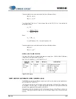
The input PGA is enabled by the IPPGAEN register bit.
REGISTER
ADDRESS
BIT
LABEL
DEFAULT
DESCRIPTION
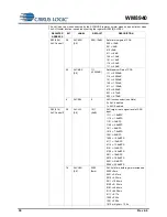
R2
Power
Management 2
2
INPPGAEN
0
Input microphone PGA enable
0 = disabled
1 = enabled
Table 3 Input PGA Enable Control


