


8
Table 1. Communication Mode Options
2.3 Assembly Options for Ease of
Manufacture
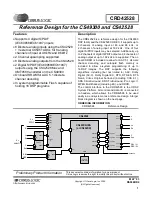
There are variety of options available on a build of
the CRD42528 that allow for different input and
output options, as well as performance differentia-
tion. This allows the same board to be used in both
low-end and high-end applications. Please note that
systems with lower performance may require exter-
nal analog Bass Management circuitry to comply
with Dolby specifications.
2.3.1 Analog Input Options
The CRD42528 supports 2, 6, or 8 channels of an-
alog input. A list of components that needs to be
populated for each configuration is shown in
Table 2. Analog Input Assembly Options
2.3.2 Analog Output Options
The CRD42528 supports 2, 6, or 8 channels of an-
alog output. A list of components that needs to be
populated for each configuration is shown in
Table 3. Analog Output Assembly Options
Mode
Populate
Do Not
Populate
SPI
R98, R99,
R10, R12,
R16, R143
R13, R14,
R18, R100,
R144,R168,
R166
I
2
C
R13, R14,
R18, R100,
R144,R168,
R166
R98, R99,
R10, R12,
R16, R143
Number of
Analog Input
Channels
Populate
Do Not
Populate
2 (L, R)
R148, R149,
R150
U18, U33, U2,
Ls, Rs, C, Sub,
SBL and SBR
Input Filters
6 (L, R, Ls, Rs,
C, Sub)
R150, U18, U33,
Ls, Rs, C, Sub,
SBL and SBR
Input Filters
R148, R149, U2,
SBL and SBR
Input Filters
8 (L, R, Ls, Rs,
C, Sub, SBL/Lz,
SBR/Rz)
U18, U33, U2,
Ls, Rs, C, Sub,
SBL and SBR
Input Filters
R148, R149,
R150
Number of
Analog Output
Channels
Populate
Do Not
Populate
2 (L/Lt, R/Rt)
U27 = CS42516
or CS42526,
L/R Output
Filters
Ls/Rs, C/Sub,
SBL/SBR Output
Filters
6 (L, R, Ls, Rs,
C, Sub)
U27 = CS42516
or CS42526,
L/R, Ls/Rs,
C/Sub Output
Filters
SBL/SBR Output
Filters
8 (L, R, Ls, Rs,
C, Sub, SBL/Lz,
SBR/Rz)
U27 = CS42518
or CS42528,
L/R, Ls/Rs,
C/Sub,
SBL/SBR
Output Filters
Summary of Contents for CS49300
Page 16: ...16 APPENDIX D SCHEMATICS Figure 6 Control and Data I O ...
Page 17: ...17 Figure 7 DSP ...
Page 18: ...18 Figure 8 External Memory ...
Page 19: ...19 Figure 9 CoDec ...
Page 20: ...20 Figure 10 External A D Converters ...
Page 21: ...21 Figure 11 L R Input Filters ...
Page 22: ...22 Figure 12 Ls Rs Input Filters ...
Page 23: ...23 Figure 13 C Sub Input Filters ...
Page 24: ...24 Figure 14 SBL SBR Input Filters ...
Page 25: ...25 Figure 15 L R Output Filters ...
Page 26: ...26 Figure 16 Ls Rs Output Filters ...
Page 27: ...27 Figure 17 C Sub Output Filters ...
Page 28: ...28 Figure 18 SBL SBR Output Filters ...
Page 29: ...29 APPENDIX E LAYOUT PLOTS GROUND PLANE VIAS ARE FLOODED Figure 19 Top Layer ...
Page 30: ...30 Figure 20 Bottom Layer ...
Page 31: ...31 Figure 21 Assembly Drawing ...
Page 50: ......