C
IRRUS
D
ESIGN
S
ECTION
7: A
IRPLANE
AND
S
YSTEMS
SR20
E
NVIRONMENTAL
S
YSTEM
P/N 11934-005
7-65
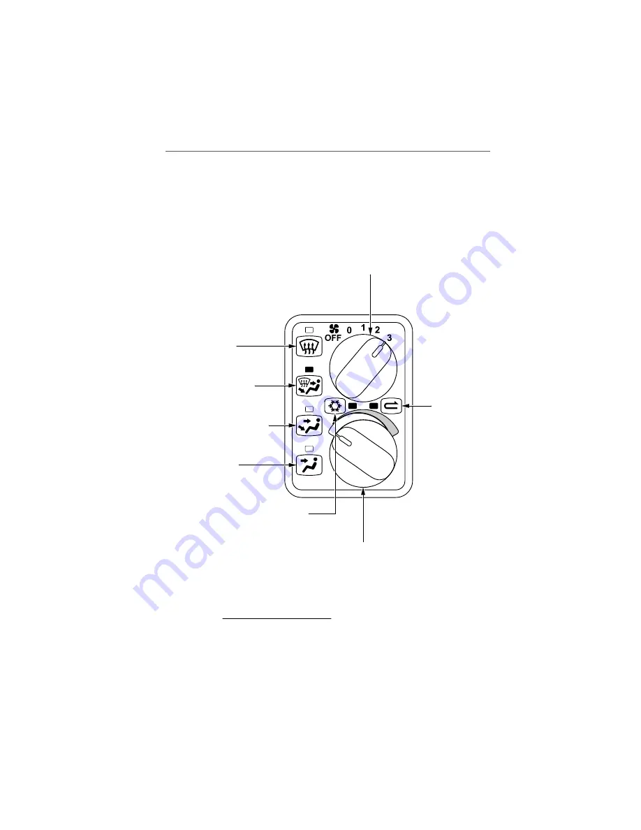
Figure 7-15:
Environmental System Operation
NOTE:
Illustration depicts settings for Emergency Procedures
Smoke and Fume Elimination.
Rotating the selector controls the volume of airflow
allowed into the cabin distribution system through
use of an electro-mechanical linkage to a butterfly
(hot air) valve in the mixing chamber on the forward
firewall. When the airflow selector fan speed is
moved to the 1, 2, or 3 position the electro-mechanical
linkage actuates the hot air valve to the full open
position and the 3-speed blower fan is turned on.
Shared airflow to the
defroster, cabin floor,
and panel outlets.
Maximum airflow to
the rear seat foot warmer
diffusers and the front
seat kickplate outlets.
Maximum airflow
to the panel and
armrest air gaspers.
Maximum airflow
to defroster.
Rotating the selector simultaneously
opens and closes the hot and fresh air
butterfly valves, permitting conditioned
(mixed) air to enter distribution system.
Air conditioning mode.
AC ON illuminated.
Maximum air
conditioning
(recirculation)
mode. AC ON
illuminated.
SR20_FM07_5359
AIRFLOW
VENTS
TEMPERATURE
If source of smoke and fume is firewall forward, turn
Airflow Selector OFF.
Reissue A


