

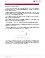
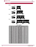
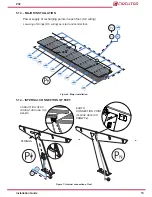


4.1.-
FEET AND WINGS
2u.
A
4u.
DIN 931
DIN 6923
DIN 934
DIN 9021
M20X130
M10
M24 Zn
M24
M20
M24
(17u
.
)
(16
u.
)
(24
u.
)
(4
u.
)
(26
u.
)
(8
u.
)
DIN 603
M10X25
M10X50
(8
u.
)
(8
u.
)
M20
(17
u.
)
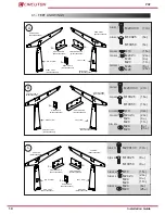
2u.
RIGHT VIEW
LEFT VIEW
[M202700000000]
WING ANGLE
[M224700000000]
[M225700000000]
ANGLE BEAM B
ANGLE BANGLE A
[M239700000000]
[M239700000000]
WING START
WING START
[M230700000000]
[M230700000000]
START FOOT
START FOOT
B
RIGHT VIEW
[M26700000000]
CENTRAL WING
4u.
[M202700000000]
WING ANGLE
[M233700000000]
CENTRAL FOOT
[M26700000000]
CENTRAL WING
DIN 931
DIN 6923
DIN 934
DIN 9021
M20X130
M10
M24 Zn
M24
M20
M24
(27u
.
)
(32
u.
)
(24
u.
)
(4
u.
)
(26
u.
)
(8
u.
)
DIN 603
M10X25
M10X50
(16
u.
)
(16
u.
)
M20
(17
u.
)
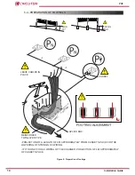
C
2u.
4u.
2u.
RIGHT VIEW
LEFT VIEW
END WING
[M225700000000]
ANGLE BEAM B
[M236700000000]
[M236700000000]
END FOOT
END FOOT
END WING
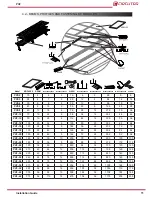
DIN 931
DIN 6923
DIN 934
DIN 9021
M20X130
M10
M24 Zn
M24
M20
M24
(17u
.
)
(16
u.
)
(24
u.
)
(4
u.
)
(26
u.
)
(8
u.
)
DIN 603
M10X25
M10X50
(8
u.
)
(8
u.
)
M20
(17
u.
)
LEFT VIEW
[M226700000000]
ANGLE BEAM C
CENTRAL FOOT
[M233700000000]
[M253700000000]
[M253700000000]
ANGLE BEAM A
[M224700000000]
[M202700000000]
WING ANGLE
10
PV2
Installation Guide
Summary of Contents for PV2 Series
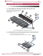
Page 1: ...INSTALLATION GUIDE M233A01 03 18A Canopies PV2...
Page 2: ...2 PV2 Installation Guide...
Page 33: ...9 FINAL FOUNDATIONS Concrete Hormig n Figure 30 Final foundations 33 Installation Guide PV2...
Page 34: ...10 INSTALLATION OF THE CHARGER Figure 31 Installation of the charger 34 PV2 Installation Guide...