Einbau- und Betriebsanleitung
Installation and Operating instructions
Instructions de montage et de service
6139-8010
07/2018
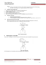
Figure 4
12.
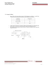
Mount the retaining plate to the SR 1000 L using two M8x16 hexagonal screws on the connecting flange. See figure 5
13.
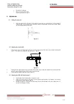
Secure the spiral spring to the lever. See figure 6
14.
Secure the actuating pin on the guide rail but do not yet tighten the M5 nut. The actuating pin is pressed from the spring onto the side of the
slot inside the lever. This allows for movement without clearance. See figure 5
Figure 5
Figure 6
15.
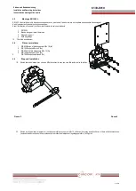
Connect the drive to a compressed air supply. Move the drive screw to the 50% stroke position. See figure 7
16.
In this position move the guide rail upward or down until the lever of the position regulator is level. Once in this position tighten the two
hexagonal screws on the guide rail.
Connection bar


