Einbau- und Betriebsanleitung
Installation and Operating instructions
Instructions de montage et de service
6139-8010
07/2018
•
Protect cables from damage.
•
Earth correctly per the field method.
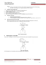
For earthing connections see figure 13.
8
Adjustments
8.1
Setting the zero point
2.
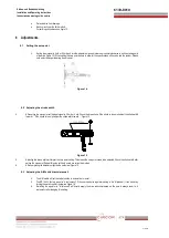
Set the input signal to 4 mA or 20 mA and turn the adjustment wheel clockwise or counter-clockwise to set the starting point
of the drive (figure 12). When setting the zero point be sure to allow for the specifications of the valve and the system. Please
note on increasing or lowering the zero point.
Figure 14
8.2 Adjusting the stroke width
4
After setting the zero point set the input signal to 20 mA or 4 mA. Check the drive stroke. If the stroke is too small, adjust the stroke width
toward ‘
+
’
.
If the stroke is too high adjust the stroke width toward ‘
-
‘
. Figure 15
Figure 15
5
Adjusting the stroke width will impact the zero point setting. This means the zero point needs to be adjusted. Check the stroke width after
setting the zero point. Repeat this step until both points are correctly adjusted.
6
After completing the adjustment tighten the set screw. Figure 15
8.3 Adjusting the A/M switch (auto/manual)
4.
The A/M switch will set the valve function to automatic or manual.
5.
The SR 1000 L factory preset is “
A (automatic)
”
. If the user needs the regulator
setting to be “
M (manual)
“ it can be set by
turning the switch counter-clockwise. Figure 16.
6.
Switching the regulator to "M (manual)
”
will directly supply the drive with compressed air.
Be sure to always reset to „A
(automatic) after changing this setting.


