background image

15  


Melter Start Up


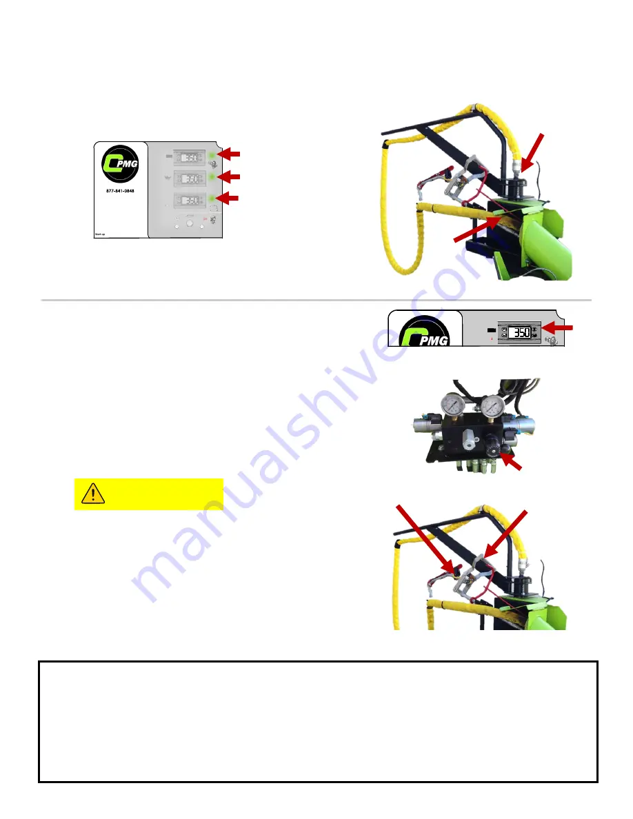
3.  PREPARE WAND 


Wait for 

all 3 

indicator lights 

GREEN 

lights to turn on. 


A) Unlock Boom 

B) Place wand in recirculation port  

4.  SETTING WAND FLOW SPEED 


Wait for material to reach desired 


temperature 


A) Set Sealant Flow Control to 

“ 0 ” 

B) Pin Wand trigger using the pin located 
above recirculation port. Open valve by pushing 
wand handle forward 

C) Slowly adjust the Flow Control knob to begin 
flow of material. 


The flow of material can be observed 
through the recirculation port. Use caution 
when in proximity to flowing hot material. 
This includes proper face and skin 
protection.
 

D) Once the material is flowing at the desired 
speed pull the handle back to stop the flow.  
 

RUNNING SEALING WAND 


With Start Up procedure complete, you are ready to begin sealing 


A) Remove pin from wand trigger 


B) Remove wand from recirculation port 


C) Squeeze wand trigger and push handle forward to began flow and begin sealing. 

B) 

B) 

B) 

A) 


CAUTION 

Summary of Contents for C1

Page 1: ...development some of the details shown in this manual may differ from your equipment We reserve the right to change the contents of the manual without notification CIMLINE COM 2601 Niagara Lane Plymouth MN 55447 763 557 1982 877 841 0848 Fax 763 557 1971 Part 161702 Rev B 05 23 2019 ...

Page 2: ...ternal Wiring Diagram 36 Tank Burner Internal Wiring Diagram 37 Oil Burner Parts list 38 Hydraulic Schematic 39 Rock Hydraulic Manifold Parts List 40 Sealant Hydraulic Manifold Parts List 41 Diesel Engine Parts List 42 43 Plumbing System Parts List 44 45 Sealing Wand 46 Heated Wand 47 Oil Burner Parts List 48 Combustion Chamber Parts List 49 Mastic Mixer Parts List 50 52 Valve Assembly Agitator Pa...

Page 3: ...The signal words DANGER WARNING CAUTION and NOTE are used to identify levels of hazard seriousness DANGER Indicates a hazardous situation which if not avoided will result in death or serious injury WARNING Indicates a hazardous situation which if not avoided could result in death or serious injury CAUTION Indicates a hazardous situation which if not avoided could result in minor or moderate injury...

Page 4: ... with sleeves rolled down and cuffs buttoned Long pants with no cuffs General Operation Safety Perform a DOT Pre Trip inspection before towing Load Melter from ground level never climb on unit to load Keep material door closed at all times except when adding material Never stand on any part of the machine Do not operate without safety cover on hose Do not touch exhaust stacks or mufflers Never tou...

Page 5: ...using loss of control Overloading can also cause unintended failures to tow vehicle The weight of your trailer listed in this manual is for the base model without any additional accessories or the weight of the sealant The weight of your trailer will vary weigh your machine to determining your Gross Vehicle Weight GVW Scales are sometimes available to use at state highway weigh stations refuse tra...

Page 6: ...6 Weight and Dimensions WEIGHT AND DIMENSIONS ARE FOR BASE UNIT WITHOUT OPTIONS WEIGHT LISTED DOES NOT INCLUDE MATERIAL WEIGHT 171 INCHES 434 cm 95 INCHES 241 cm BASE WEIGHT 6400 lb ...

Page 7: ... Maximum Tank Sealant Capacity 230 Gallons 165 Gallons Product specification may change without notice Images contained in this manual may differ from the actual product To maintain safe operation of trailer do not fill tank more than 75 of tank size WARNING ...

Page 8: ...5 Oil Temperature Gauge Displays the heat transfer oil temperature 6 Aggregate Hopper Hopper for aggregate that will be mixed to create mastic 7 Ignition Switch Engine on and off 8 Sealing Wand Dispenses sealant 9 Sealant Flow Control Control the flow rate of sealant 10 C1 Mastic Control Panel Controls for applying mastic 11 Mastic Flow Control Controls the amount of aggregate that mixes into mast...

Page 9: ...9 Base model shown Your model may included additional options or variations 8 1 2 4 5 6 7 9 11 12 13 14 10 3 ...

Page 10: ...Activate Deactivate the rock heat chamber Inside Mastic Control Panel is the temperature control module Contact CIMLINE Technical support before changing any settings Main Control Panel The main control panel is used to operate the melter control system Controls located on the cover are for operating in auto mode only OFF Shuts down Agitator Burner Hose and Pump RUN Allows the preprogrammed contro...

Page 11: ...11 Inside the Main Control Panel box is a Sub Control Panel See the next page for detailed explanation of use IMLINE ...

Page 12: ...ounter clockwise or Clockwise If the switch is in the center position the agitator will not rotate 5 Low Flow Switch Some sealants dispense best at low flow rates 4 if they dispense unevenly switch the Auto Manual switch to Manual and place the Low flow switch to the For material flow Lower than 4 This will make the material pump only rotate when the wand trigger is pressed resulting in more consi...

Page 13: ...13 Sub Control Panel Controls and Their Functions 1 2 3 4 5 6 7 8 9 10 11 12 IMLINE ...

Page 14: ...ll material must be clean Keep all foreign matter out of melting tank 1 Open the material door a and place the block of material b on the open door against the holder c 2 Push door to the closed position TO AVOID CONTACT WITH HOT SEALANT DO NOT DROP MATERIAL INTO THE MELTER WITH DOOR OPEN LOADING OPERATOR MUST WEAR PROTECTIVE CLOATHING COVERED ON PAGE 4 LOAD MATERIAL FROM GROUND ONLY NEVER CLIMB O...

Page 15: ...just the Flow Control knob to begin flow of material The flow of material can be observed through the recirculation port Use caution when in proximity to flowing hot material This includes proper face and skin protection D Once the material is flowing at the desired speed pull the handle back to stop the flow RUNNING SEALING WAND With Start Up procedure complete you are ready to begin sealing A Re...

Page 16: ... KEY TO PREVENT STARTING ALLOW THE CONVEYER SCREW TO COOL DOWN BEFORE REMOVING HOPPER GRATE AND UNCLOGGING SCREW DO NOT LOAD ROCK INTO HOPPER WITHOUT GRATE PROPERLY INSTALLED 3 Once you observe rock begin to drop into the mixing chamber CLOSE the Mastic Gate 1 Set Rotary Switch on Mastic Control Panel to ROCK ONLY 2 OPEN the Mastic Gate to draw rock into heat chamber Follow Start Up Procedures 1 2...

Page 17: ...te Machine is configured to prioritize the mastic mixing chamber wand will not operate while the mastic system is in operation The Sealant Flow Control is located below the MAIN CONTROL PANEL The Rock Flow Control is located below the MASTIC CONTROL PANEL NOTICE 9 CLOSE the Mastic Gate to stop dispensing Note Instructions will provide a 2 1 Rock to Sealant Mixing Ratio for alternative mixing ratio...

Page 18: ...HAMBER CLEANOUT 2 OPEN the Mastic Gate to purge Mixing Chamber 3 CLOSE the Mastic Gate after material stops flowing 4 Set Rotary Switch to OFF Clean Out Procedure Melter Cleanout Procedure 1 SETUP A Place wand in Recirculation Port B Pin wand trigger and open valve by pushing handle forward D Set flow to 9 C Set Control Panel rotary switch to CLEAN OUT Hose Clean out Let pump run in CLEAN OUT for ...

Page 19: ... an application temperature of 380 F 193 C With some sealants it may be require a change to the controller to achieve the appropriate application temperature To achieve this open the control box and alter the Sealant Temperature Controller top controller by following the directions below Decrease Increase A 1 Press the SET button 2 SP1 is displayed 3 Press the SET button 4 Current Temperature is d...

Page 20: ... excessive X Service air cleaner element X Inspect material flow plumbing X Inspect burner nozzle electrode head pos adjust if necessary X Change engine oil and oil filter X Grease agitator bearing block load adapter X Inspect fuel filter replace if dirty X Inspect Diesel burner electric eye clean if dirty X Grease wheel bearings X Inspect chamber lining replace if excessive cracking X Inspect sta...

Page 21: ...housing Reference engine manual for washing instructions CIMLINE recommends stocking replacement filters Fuel Use high quality detergent oil of API American Petroleum Institute service class CC or CD grade Select the viscosity based on the air temperature at the time of operation Reference your engine manual for other recommendations Packing Lock Nuts 2 Slight Drip in this area is normal Material ...

Page 22: ...n loose Do not attempt to repair cracks CONTACT WITH LINING MAY CAUSE SKIN OR EYE IRRITATION WEAR LONG SLEEVE GLOVES AND GOGGLES WHEN INSPECTING LINING Remove burner mount bolts a and pull out burner and mount Inspect lining b for excessive cracking If cracks exceed guidelines contact your CIMLINE dealer to purchase a replacement kit Burner This machine has 2 burners There are several items that n...

Page 23: ...r those are loose remove the two bolts in the back of the C1 and set the upper cover aside Second remove the 4 bolts holding the bottom cover in place Lift the cover straight up until it has cleared the material pump Set the lower cover aside a a Use a torque wrench with an extension and check the 6 nuts from the upper flange c These need to be set to 30 Ft pounds c Use a torque wrench with an ext...

Page 24: ...es Heat plumbing and valve to melt Low hydraulic level Check oil level Foreign object lodged in line Remove foreign object Pump damaged Replace pump Material pump rotates but does not pump material Pump rotating in wrong Reverse pump switch Pump inlet line plugged Check sealant tank grid and lines for Too much material left in lines from previous use Heat plumbing and valve to melt material Pump w...

Page 25: ...AT AIR OIL C1 6 8 GALLONS PER INCH Material Depth Gallons Material in Tank 2 13 6 4 27 18 6 40 78 8 54 37 10 67 96 12 81 56 14 95 15 16 108 74 18 122 34 20 135 93 22 149 52 The amount of material can be calculated by measure the depth of material in the tank INSULATION ...

Page 26: ...additives to make the oil conform to different applications YOU MUST CLARIFY with the supplier that the oil is to be used in a heat transfer system to avoid any potential problems Oil is also available from CIMLINE in 5 and 30 gallon 19 and 114L containers for ship out FLASH POINT Test in which an open container of oil is heated until an open flame will flash when passed over the fumes FIRE POINT ...

Page 27: ...s Engine oil transmission fluid etc adversely affects each manufacturers formula C1 Hydraulic Reserve Capacity 30 Gallons 114L Hydraulic Oil Type Conoco MV32 or equiv Diesel Fuel Capacity 30 Gallons 114L Diesel Fuel Type ASTM D975 No 2 Heat Transfer Oil Capacity 21 Gal 80L Heat Transfer Oil Type See Specs On Previous page Agitation Drive Relief Setting 1100 PSI 76 bar Material Pump Drive Relief Se...

Page 28: ... Burner Internal Wiring Diagram 37 Oil Burner Parts list 38 Hydraulic Schematic 39 Rock Hydraulic Manifold Parts List 40 Sealant Hydraulic Manifold Parts List 41 Diesel Engine Parts List 42 43 Plumbing System Parts List 44 45 Sealing Wand 46 Heated Wand 47 Oil Burner Parts List 48 Combustion Chamber Parts List 49 Mastic Mixer Parts List 50 52 Valve Assembly Agitator Parts List 53 Miscellaneous Par...

Page 29: ...29 Trailer Wiring Diagram Note Brake controller is required on vehicle to active the brakes on the trailer ...

Page 30: ...30 Sealant Control Panel Wiring Diagram SEALANT MANIFOLD C1 MASTIC WIRE HARNESS C1 MASTIC WIRE HARNESS HEATED HOSE HEATED HOSE ...

Page 31: ...31 Sealant Control Panel Wiring Diagram ...

Page 32: ... 75552 1 F 130113 TYCO RELAY V23234C1001X008 2 G FUSE BLOCK 1 H LUG 1 I YELLOW LED LIGHT 2 J 152119 FUSE HOLDER 1 K GREEN LED LIGHT 3 M TERMINAL STRIP DIN 1 N 130342 RELAY BASE 2 R 130883 SELECTOR SWITCH 1 13 130834 CONTROLLER MATERIAL 1 14 130835 CONTROLLER OIL 1 15 130836 CONTROLLER HEATED HOSE 1 16 111204 TOGGLE SWITCH 1 ...

Page 33: ...ROL PANEL 1 2 DIN TERMINAL 1 3 130834 CONTROLLER MATERIAL 1 4 130883 SELECTOR SWITCH 1 5 130122 SWITCH 1 6 130921 CONTROL PANEL 1 7 152119 FUSE HOLDER 1 8 430386 PLATE CONTROL 1 SEE MASTIC INTERNAL WIRING DIAGRAM ON PAGE 33 FOR WIRING CONNECTIONS TO THE PLUGS ABOVE ...

Page 34: ...g Diagram Number Color AWG Wire Gauge 1 Green Yellow stripe 12 2 PURPLE 16 3 Yellow 16 4 Light Blue 16 5 Orange 16 6 Red 16 Number Color AWG Wire Gauge 7 White 16 8 Black 16 9 Red 12 10 White 16 11 Red 16 12 Green 16 ...

Page 35: ...ction 1 White Hose A C Voltage 2 Black Hose A C Voltage 3 Red Black Stripe Burner Power 4 Red Battery 5 White Burner Enable 6 Red Micropanel Accessory Input 7 Green Yellow Stripe Battery 8 Green Generator Excite 36 Brown Burner Error to Micropanel ...

Page 36: ...HITE POWER FROM RELAY 3 WHITE OR RED MAIN POWER TO BURNER 4 WHITE BURNER INPUT 5 8 YELLOW CAD CELL 9 17 GROUND 18 ORG MOTOR AND VALVE POWER 19 RED MOTOR AND VALVE POWER 20 BLUE IGNITER POWER 21 RED IGNITER POWER 22 23 VALVE POWER ENABLE GND MTR CAD CELL MOTOR GND IGN IGNITER GND VLV ALARM VALVE 30 10 Black Brown White 8 6 5 4 WHITE Red RELAY ...

Page 37: ...37 Tank Burner Internal Wiring Diagram ...

Page 38: ...91 MOTOR OIL BURNER 5 155001 PUMP OIL 6 152106 ELECTRODE ROD INS ASSY 7 152128 GASKET BURNER FLANGE 8 152173 IGNITION TRANSFORMER ASSY 9 152200 OIL VALVE 10 200352 PRIMARY CONTROL ASSY 11 120443 AIR TUBE 12 120466 BURNER HEAD TUBE 13 152398 AIR INLET GUIDE 14 152399 COUPLING 15 152466 BLOWER WHEEL 16 152105 ELECTRIC EYE ASSY 130166 FUEL PRESSURE GAUGE NOT SHOWN ...

Page 39: ...39 Hydraulic Schematic For Compressor Hydraulics see Supplement manual ...

Page 40: ...2587 RELIEF VALVE SET AT 800 PSI 4 SPOOL AND COIL KIT FOR MASTIC AND AGGRIGATE AUGER SPOOL FOR MASTIC AND AGGRIGATE AUGER 172225 COIL FOR MASTIC AND AGGRIGATE AUGER 5 172589 SPOOL AND COIL KIT FOR MASTIC ACTUATOR 172557 SPOOL FOR MASTIC ACTUATOR 172585 COIL FOR MASTIC ACTUATOR 6 172563 ROTARY FLOW CONTROL ...

Page 41: ...T AT 800 PSI 4 172226 SPOOL AND COIL KIT FOR MATL PUMP 172224 SPOOL FOR MATL PUMP 172225 COIL FOR MATL PUMP 2 REQ D 5 172589 SPOOL AND COIL KIT FOR TFC 172557 SPOOL FOR TFC 172585 COIL FOR TFC 6 172583 SPOOL AND COIL KIT FOR AGITATOR 172584 SPOOL FOR AGITATOR 172585 COIL FOR AGITATOR 2 REQ D 7 172563 ROTARY FLOW CONTROL ...

Page 42: ... LH 3 422167 PLATE ENGINE MOUNT RH 4 100126 WASHER FLAT 38 5 153619 MUFFLER COWL 6 155143 FLEXABLE EXHAUST 7 155927 HYD PUMP FOR DUAL PUMP 8 200543 BATTERY BOX 9 152047 SEALENT ISOLATER 10 111108 LOFA CONTROL SWITCH 11 150212 BATTERY 26 26R 50 WET 12 111111 AIR FILTER 13 111337 OIL FILTER 14 110947 BELT A 29 15 130431 GENERATOR 16 155266 IGNITION KEY 17 111372 FAN BELT ...

Page 43: ...43 Engine Components ENGINE MAINTENCE KIT PART NUMBER 406599 PART DESCRIPTION 1 170407 RETURN FILTER 2 170169 FUEL FILTER BURNERS 3 111457 FUEL FILTER ENGINE 4 111111 AIR FILTER 5 111337 OIL FILTER ...

Page 44: ...0 155997 ROD ADAPTER 11 429584 PLATE BEARING MNT 12 407838 COUPLING WELDMENT 13 120682 PIPE NIPPLE 1 0 X 3 0 14 120774 BUSHING HEX 1 5 X 1 15 155920 TEE WELD 16 120611 2 PIPE UNION 17 409484 FLANGE SUPPORT WELD 18 152127 GASKET 3 19 406162 OFFSET FLANGE WELD 20 429818 PLATE BACKER 21 120803 PUMP 22 120029 PIPE NIPPLE 2 X 3 23 430167 PLATE VALVE BRACE 24 170602 MOTOR 45 CU IN 25 111737 SPRING PIN 1...

Page 45: ...45 Sealant Plumbing Components ...

Page 46: ... 75 1 6 407872 SUB HANDLE 1 21 111725 THRUST WASHER 2 7 407863 WAND SUB WELD 1 22 100275 COTTER PIN 09 X 75 1 8 407862 HANDLE 1 23 100207 25 NUT 2 9 407232 SWIVEL TIP 1 24 100169 NUT PLASTIC LOCK 38 3 10 403905 VALVE LEVER 1 25 100126 WASHER FLAT 38 2 11 170635 SWIVEL 1 26 100125 WASHER FLAT 31 1 12 155297 SPRING 1 27 100092 WASHER SPLITLOCK 31 1 13 155272 SLEEVE W LINK 1 28 100022 HHCS 38X2 5 1 1...

Page 47: ...47 Heated Sealing Wand PN 155865X For use with 18 Hose PN 200622 Complete Hose and Wand Assembly PN 409134 Optional Wand Attachments Available See page 57 for details ...

Page 48: ... TANK 2 172619 DIESEL TANK 3 172127 RETURN FILTER ASSY NON COMPRESSOR 4 170407 ELEMENT RETURN FILTER NON COMPRESSOR 5 152044 FILLER CAP ASSY 6 171631 SIGHT GAUGE 7 172186 SUCTION STRAINER 8 155396 FUEL GAUGE CAP 9 120743 FUEL SHUT OFF VALVE 10 170169 FUEL FILTER 10 7 1 1 2 6 3 4 5 8 9 9 ...

Page 49: ...BER LINING KIT 1 2 402898 BURNER MOUNT 1 3 402893 HEAT CHAMBER SKIN 1 4 417041 INSPECTION COVER 1 5 152487 INSULATION HEAT CHAMBER 1 6 100125 WASHER FLAT 31 16 7 100093 WASHER SPLIT LOCK 38 2 8 100092 WASHER SPLITLOCK 31 8 9 100068 NUT HEX 31 8 10 100015 BOLT HEX 3 8 16 X 3 4 2 11 100006 HHCS 31 X 1 0 8 ...

Page 50: ...50 Mastic Mixer Assembly ...

Page 51: ...D 1 16 430449 PLATE TOOL HOLDER 1 17 409832 AUGER GUARD 1 18 409556 TOOL CAB SUB WELD 1 19 430382 PLATE INTAKE GUARD 1 20 409557 HOPPER WELD 1 21 430401 PLATE MOTOR GUARD 1 22 200644 CONVEYENCE FLIGHTING 1 23 156138 LINER 1 24 156131 TROUGH 1 25 430398 PLATE COOLER MOUNT 1 26 172092 COOLER HYDRAULIC ASA 1 27 409564 CHUTE SUPPORT WELD 1 28 427485 PLATE MANIFOLD MOUNT 2 29 430391 PLATE CHUTE SUPPORT...

Page 52: ...CHAIN NO 50 1 16 110683 BEARING FLANGE 62 1 17 110294 KEY 38 X 2 00 LG 1 18 100486 HHCS 50 X 4 5 FULL THD GR5 ZP 1 PART DESCRIPTION QTY 19 100463 WASHER FLAT SAE 31 5 20 100242 NUT HEX 38 24 UNF 1 21 100221 SPRING PIN 3 16 X 1 50 1 22 100211 WASHER FLAT SAE 38 4 23 100163 HHCS 38 X 3 50 4 24 100126 WASHER FLAT 38 8 25 100125 WASHER FLAT 31 8 26 100093 WASHER SPLIT LOCK 38 16 27 100092 WASHER SPLIT...

Page 53: ...7 ELBOW BULKHEAD 12MJ 12MJ 90 2 5 172645 18 FLEX HOSE 12 FJIC 2 Agitation System Parts List 6 7 4 5 3 2 1 PART DESCRIPTION 1 110294 KEY 3 8 X 2 2 170467 MOTOR AGITATION 3 170449 LOAD ADAPTER M 4 416670 AGITATOR MOTOR MOUNT 5 405107 AGITATOR 6 100093 SPLIT WASHER 7 100877 HHCS 38 X 3 75 PART DESCRIPTION 153772 SEAL KIT FOR MOTOR MAINTENANCE KIT ...

Page 54: ...N 2 16 150212 BATTERY 26 26R 50 WET 1 17 140711 TIRE ASSEMBLY 2 18 140713 HITCH PINTLE RING 1 140714 HITCH BALL 2 5 16 IN 1 19 140330 JACK 5000 LB 1 20 130405 GROMMET FOR TAILLIGHT 2 21 130403 TAILLIGHT LED OVAL 2 22 130402 CLEARANCE LIGHT RED 3 23 130375 CLEARANCE LIGHT AMBER 2 24 130374 CLEARANCE LIGHT RED 2 25 130130 THERMOMETER 24 2 26 130050 SWITCH BREAKAWAY NO 2010 1 153638 CABLE FOR BREAKAW...

Page 55: ...55 Miscellaneous Parts ...

Page 56: ...3 4 5 8 7 PART DESCRIPTION 1 152105 ELECTRIC EYE 2 200352 PRIMARY CONTROL 3 130113 RELAY HEATED HOSE BURNER 4 152399 COUPLING 5 200482 CONTROLLER 6 153537 FUSE 10 AMP QTY 5 7 130097 THERMOCOUPLE OIL 8 153621 THERMOCOUPLE PUMP 9 153644 FUSE ABC 15 ...

Page 57: ...64Z 1 4 SEALING TIP 403163Z 3 8 NPT X 3 1 2 LONG TUBE ANGLED TIP MAY BE FLATTENED IN FIELD FOR DIFFERENT APPLICATIONS 3 4 NPT INLET 120567 REDUCER REQUIRED 3 8 SEALING TUBE 416968 3 4 X 3 8 REDUCER 120567 PIVOTING SHOE 403137 2 OR 3 WIDE BAND 3 4 NPT INLET 3 8 OD ORIFICE 4 1 2 OD PLATE UNIFORM BAND PROVIDED BY DISC SHAPE SEALING DISC 2 5 404528 SEALING DISC 3 5 403162 2 OR 3 WIDE BAND 3 4 NPT INLE...

Page 58: ... Rock to Sealant Ratio is most common for Mastic Applications 9 on the Dial for the Rock Flow Control and 5 on the Dial for the Sealant Flow Control Rock Sealant Ratio Sealant Flow Control Under main control panel 1 2 3 4 5 6 7 8 9 Rock Flow Control Under mastic control panel 1 1 2 2 1 3 3 1 5 1 4 2 1 3 1 More Sealant 5 2 5 1 7 1 3 1 6 3 2 1 5 1 2 1 Most Common 7 2 3 1 8 1 4 1 2 1 8 2 7 2 1 6 1 3 ...

Page 59: ...anual Before Operating Eqiupment STAY CLEAR OF ACTUATOR WHILE ENGINE IS RUNNING MANUFACTURER RECOMMENDS ASTM D975 NO 2 D S15 THE GENERAL AUTOMOTIVE DIESEL ENGINE ALL PURPOSE FUEL OIL OR EQUIVALENT WHICH FULLY MEETS THE ABOVE REQUIREMENTS DIESEL FUEL ONLY CHECK HYDRAULIC OIL LEVEL BEFORE STARTING HYDRAULIC OIL 1 CHECK SIGHT GAUGE TO VERIFY FLUID LEVEL 2 CHANGE HYDRAULIC OIL FILTER AND INSPECT STRAI...

Page 60: ...ses heated hoses with heated wands which use the above scale for pro rated coverage For replacement parts that are purchased the 60 day period will commence from the date of distributor to end user invoice A copy of the invoice will be required as proof of in service date If invoice is not provided policy will revert back to the original factory invoice date Warranty does not apply to defects caus...

Reviews: