10
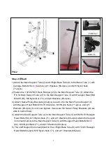
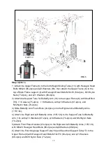
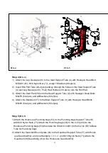
Step 3 (
FIG 3)
1
)
Attach the Upper Frame (6) to the both Weight Sliding Tubes (13) with Hexagon Head
Bolts M8x20 (66-2pcs) and
φ
9 Washers (69). then attach the Upper Frame (6) to the
top of Main Frame support (3) with Hexagon Head Bolts M10x70 (60-2pcs), M10 Nylon
Nuts (71-2pcs), and
φ
11 Washers (68-4pcs).
2) Attach the Support Tube for Butterfly Arm (10) to the Upper Frame (6) with Shaft Bolt
(55),
∮
16 sleeve (75-2pcs)
∮
16 Washers, with
φ
13 Washers (67-2pcs), and
M12Nylon Nuts (70-2pcs).
3) Slide Butterfly Arm Foam Rolls (34-2pcs) onto the Right and Left Butterfly Arms
(11R,12L).
4) Attach the Right and Left Butterfly Arms (11R,12L) to the Support Tube for Butterfly
Arm (10), with
φ
13 Washers (67-2pcs),
φ
16 Washers (74-2pcs) and M12Nylon Nuts
(70-2pcs).
5)Attach Front Press Handles (23-2pcs) to the Right and Left Butterfly Arms (11R,12L)
with M8x20 Hexagon Head Bolts (66-2pcs) and
φ
9Washers (69-2pcs).
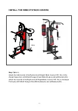
6) Attach the Punching bags Support Tube(16) and Seed ball Support Tube(17) to the
Upper Frame (6)with Hexagon Head Bolts M10x170 (63-2pcs) and
φ
11 Washers
(68-4pcs) and M10 Nylon Nuts (71-2pcs)
PART 10
FIG 3
Summary of Contents for CD-2006A
Page 4: ...3 OVERVIEW DRAWING...


