background image

18

MAINTENANCE

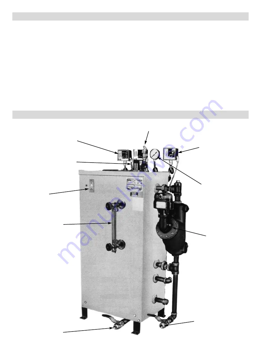
RENEWAL PARTS IDENTIFICATION

Drain Blowdown Valve

Drain Blowdown Valve

Water Level Sight Glass

On/Off Switch and
Pilot Light

Steam Outlet

Operating Pressure Control
Range 10-300 Psi

Safety Valve

Manual Reset High
Limit Control

Pressure Gauge, 0-600 Psi

McDonnell & Miller #194
Low Water Cutoff/Pump

Check Valve/Water Inlet
(not shown)

READ COMPLETELY BEFORE STARTING WORK

1.

Disconnect boiler from electric power supply at 

main safety

switch or fuse panel.

Then, turn boiler switch to “off” position.

2.

On automatic feed units, close valve on incoming water line. Drain
boiler completely of water.

3.

Open boiler door to expose heating element.

4.

Disconnect wire (electric) leads connecting element to main power
system of boiler. Again note wire connections to facilitate
reassembly. Proceed to remove (6) 5/16-18 bolts from flange.

5.

Thoroughly clean boiler flange of all foreign material. Be certain
no part of old gasket remains on boiler flange.

6.

Apply “Slic-Tite” Gasket Compound or equal to both surfaces of
new gasket with supplied replacement element. Proceed to install
element flange assembly with gasket between boiler flange and
element flange. In doing this, be careful to align flange holes so
wire connection terminals on element assembly are in line with
previously disconnected wire leads to facilitate easy connections.

7.

When all (6) flange bolts are tight, connect all wires to terminals.
Make certain wires are clean and bright to assure good electrical
contact and nuts on screws are firmly secured.

WARNING:

Avoid use of chemical cleaning com-

pounds. Follow maintenance instructions.

8.

Open water valve so water supply can reach boiler feed mecha-
nism.

9.

Put main safety switch to “on” position.

10.

Turn boiler to “on” position.

11.

As boiler automatically refills, observe the new flange assemble
for possible leaks. If water is noticed, to bolts must be retightened.
Before doing this, turn the boiler off at the main fuse safety switch. 

12.

As boiler is heated to working pressure, check flange assembly
again for leaks.

WARNING:

Avoid the use of chemical cleaning com-

pounds. Follow maintenance instructions

Summary of Contents for CHPES-100A

Page 1: ...50 6 17 CHPES 135A 13 9 136 30 5 410 8 50 4 50 8 17 1 30 CHPES 160A 16 1 157 5 30 5 475 7 60 3 60 7 22 5 CHPES 180A 18 4 180 30 5 543 8 60 4 60 8 22 5 Chromalox DIVISION 4 SECTION CHPES SALES REFEREN...

Page 2: ...lt Hole Typical Steam Outlet Sight Glass Element Element Access Door Operating Pressure Controls Control Circuit Fuse Control Circuit On Off Switch with Pilot Light 5 8 7 16 Bolt Hole Typical 1 1 4 Dr...

Page 3: ...A minimum distance of 18 between boil er and any combustible material must be maintained 3 Complete all piping to boiler Connect water line to tagged fitting on the motor and pump assembly if used or...

Page 4: ...rical connections are sufficiently tightened 6 WARNING Substitution of components or modifica tion of wiring system voids the warranty and may lead to dangerous operating conditions 7 SPECIAL INSTRUCT...

Page 5: ...tor 10L 30L 20L IT1 IT3 IT2 CR Wire Color Code B Black BR Brown R Red O Orange Y Yellow G Green BL Blue W White Diagram 3 2PS BR Heater Contactor Feed Water Boiler On 3 GND B FU9 B 1PB Off 1 GND 1 HTR...

Page 6: ...tomer Connect Feed Water Motor 10L 30L 20L IT1 IT3 IT2 CR Wire Color Code B Black BR Brown R Red O Orange Y Yellow G Green BL Blue W White Diagram 5 2PS BR Heater Contactors Feed Water Boiler On 3 GND...

Page 7: ...Customer Connect Feed Water Motor 10L 30L 20L IT1 IT3 IT2 CR Wire Color Code B Black BR Brown R Red O Orange Y Yellow G Green BL Blue W White Diagram 7 2PS BR Heater Contactors Feed Water Boiler On 3...

Page 8: ...ion CR FU19 FU20 FU21 7L1 7L3 7L2 1 Mtr Customer Connect Feed Water Motor 10L 30L 20L IT1 IT3 IT2 CR C1 Wire Color Code B Black BR Brown R Red O Orange Y Yellow G Green BL Blue W White Diagram 9 FU 1...

Page 9: ...5 FU26 FU27 9L1 9L3 9L2 1 Mtr Customer Connect Feed Water Motor 10L 30L 20L IT1 IT3 IT2 CR Wire Color Code B Black BR Brown R Red O Orange Y Yellow G Green BL Blue W White Diagram 11 FU 1 2 3 FU 4 5 6...

Page 10: ...r Contactor CR FU22 FU23 FU24 8L1 8L3 8L2 1 Mtr Customer Connect Feed Water Motor 10L 30L 20L IT1 IT3 IT2 CR Wire Color Code B Black BR Brown R Red O Orange Y Yellow G Green BL Blue W White Diagram 13...

Page 11: ...switch If low water cutout is automatic reset pump or solenoid will return water level to normal If low water cutout is manual reset then manual reset button on McDonnell Miller low water cutoff cont...

Page 12: ...de of boiler Customer Supplied 2 Turn on boiler and allow pressure to build up to operating pressure 3 Only open globe valve at quarter turns at first introducing smaller amounts of steam into process...

Page 13: ...CLOSED and the BOILER ON should light up again Now turn the wheel on the large timer until the OFF tab passes the TIME NOW arrow The BOILER ON light should go out and the valve should begin to open O...

Page 14: ...s its open position until circuit balance is achieved The slightest change in the pressure of the controlled medium will cause a change in the number of elements energized to compensate for it thus ke...

Page 15: ...OF SEQUENCER 1 With boiler off remove wiring from pressure control on sequencer low voltage terminal board 2 Turn on boiler to supply the voltage to the sequencer Short ter minal R and B for countercl...

Page 16: ...n accordance with local and national electrical codes Refer to boil er instruction for manual wiring diagram 5 If pump is located less than 30 feet from boiler a second check valve is required WATER F...

Page 17: ...ensure the boiler has ade quate water 3 A monthly inspection should be made of internal wiring All elec trical connections should be checked for tightness A check for water or steam leaks should also...

Page 18: ...y Slic Tite Gasket Compound or equal to both surfaces of new gasket with supplied replacement element Proceed to install element flange assembly with gasket between boiler flange and element flange In...

Page 19: ...039 004 5 Step Motor Driven Sequencer 323 121505 001 10 Step Motor Driven Sequencer 323 121505 002 6 Step Solid State Sequencer 323 300107 015 10 Step Solid State Sequencer 323 300107 015 Siphon Tube...

Page 20: ...BLVD OGDEN UT 84404 Phone 1 800 368 2493 www chromalox com Limited Warranty Please refer to the Chromalox limited warranty applicable to this product at http www chromalox com customer service policie...

Reviews: