background image


Terra Manager 

Terra User Manual 

83 

020-102838-10 Rev. 1 (05-2020) 
Copyright

©

 2020 Christie Digital Systems USA Inc. All rights reserved. 

2.


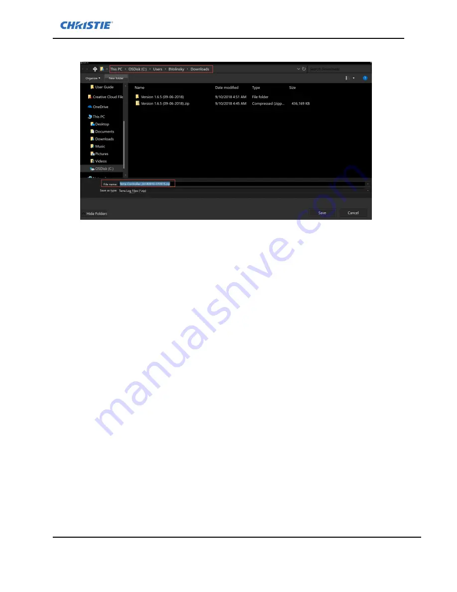
When prompted, specify the file location and note the file name and type. 


3.


Click 

Save

How to Activate Managed Devices Key 

Controllers are shipped with a key for 24 devices (TX/RX). If your configuration has more than 24 

devices, you need to purchase an upgrade. Contact your Christie Sales Representative to review your 

system design and obtain an upgrade. 

1.


Navigate to the Global page. 

2.


Click 

Get Managed Devices Key

Summary of Contents for Terra

Page 1: ...Terra User Manual 1 020 102838 10 Rev 1 05 2020 Copyright 2020 Christie Digital Systems USA Inc All rights reserved User Manual 020 102838 10 Terra ...

Page 2: ...e product outdoors unless such product is protected from precipitation or other adverse weather or environmental conditions and the ambient temperature is within the recommended ambient temperature set forth in the specifications for such product g Defects caused by normal wear and tear or otherwise due to normal aging of a product The warranty does not apply to any product where the serial number...

Page 3: ...all rights including copyright and all other intellectual property rights in and to the Software and all copies thereof regardless of form or media This license is not a sale of any rights in or to the Software or any copy thereof Licensee acquires no right whatsoever to the Software except the right to use the Software in accordance with the terms of this License 2 Grant of License Christie grant...

Page 4: ...tware is provided as is and Christie makes no warranty of any kind with regard to the Software Christie will not be liable for errors contained in the Software orin connection with the performance or use of the Software Christie does not warrant that the Software is free from any defects or that it will operate uninterrupted Christie warrants that the media on which the Software is distributed wil...

Page 5: ...lity and Waiver Any provision of this Agreement which is held by any court to be unenforceable or invalid will be deemed severed from this Agreement without affecting any other provision of this Agreement No waiver by Christie of any particular default or omission committed by Licensee will affect or impair the right of Christie in respect of any subsequent default or omission of the same or a dif...

Page 6: ...联苯醚 PBDE Audio Video input PCB 音影输入卡 X O O O O O System board PCB 主板 X O O O O O Mechanical enclosure 机械附件 X O O O O O Note O indicates that the concentration value of the particular hazardous substance contained in all the homogeneous materials for this part according to EIP A EIP B EIP C is below the stipulated levels in China SJ T11363 2006 表示该有毒有害物质在该部件所有均质材料中的含量均在SJ T11363 2006规定的限量要求以下 X ind...

Page 7: ...械組件 Mech anical enclosure 備考1 超出0 1 wt 及 超出0 01 wt 係指限用物質之百分比含量超出百分比含量基準值 Note 1 Exceeding 0 1 wt and exceeding 0 01 wt indicate that the percentage content of the restricted substance exceeds the reference percentage value of presence condition 備考2 係指該項限用物質之百分比含量未超出百分比含量基準值 Note 2 indicates that the percentage content of the restricted substance does not exceed the percentage of reference value o...

Page 8: ...ceiver Ports and Status Indicators 18 Terra Controller Ports and Status Indicators 19 System Configuration and Setup 19 Connecting a computer 19 Computer Requirements 19 Connecting the Controller to the Network 20 Resetting TXs and RXs to Factory Defaults 21 Terra Startup Assistant 22 Start Terra Startup Assistant on your PC 22 Configure a New Controller 23 View and Delete Messages 25 Terra Startu...

Page 9: ...ng Additional Data Streams 67 Starting or Stopping Video Streams 68 Operation Mode Create a Multiview Layout 69 Operation Mode Transmitter Properties 73 Operation Mode Organizing Layouts and Sources 76 Operation Mode Delete a Layout 76 Operation Mode Recall a Layout 76 Global Page 77 Configure Controller Settings 79 Enable Controller Redundancy 79 Set a Network Time Protocol NTP Server 79 Set Date...

Page 10: ...y 94 Reference Information 95 Software Versioning 95 Importing Device IP Configuration 95 Videowall Specifications 95 Protocol Ports 96 RS 232 96 RGMII 1000Base T Interface 96 Multichannel I2S Audio Interface 96 Ancillary I2S Audio Interface 96 RGMII USB 2 0 interface 97 Infrared 97 Cabling 97 HDCP 98 Color space Conversion 98 HDMI Audio Routing 98 IR Control 98 Specifications 99 Sample Applicatio...

Page 11: ...cument are for example purposes only and the hardware and software illustrated may differ from your version Variable text that is entered by a user is italicized in this document for example in the text 6 digit serial number the 6 digit serial number would be replaced by the actual serial number Related Documentation Access the latest documentation from the Christie website at http bit ly TerraDow...

Page 12: ...D SHOCK HAZARD Do not attempt operation unless the power cord power socket and power plug meet the appropriate local rating standards Caution If not avoided the following could result in minor or moderate injury SHOCK HAZARD Only use the AC power cord provided with the product or recommended by Christie TRIP OR FIRE HAZARD Position all cables where they cannot contact hot surfaces be pulled be tri...

Page 13: ...ractices page 17 4 Install and setup the equipment Install and Setup page 18 Also refer to the Install and Setup Guides 5 For Controlled System log in to the Terra Manager Logging in to the Terra Manager page 28 6 Optionally use the Terra Manager to set up Stringent Security Enable Stringent Security page 80 7 Use the Terra Manager to set up users Users page 77 8 Use the Terra Manager to review gl...

Page 14: ...g LED indicators providing quick status The Transmitter processes audiovisual sources and control signals to deliver uncompressed zero frame latency artifact free content over 10G networks The Terra Transmitter supports video resolutions up to 4K 60Hz and accepts various port connections including HDMI 2 0 USB HDCP 2 2 DisplayPort 1 2 serial RS 232 EDID and more This powerful and flexible device d...

Page 15: ... desktop PCs because they frequently migrate and this eliminates configuration time for IT staff Terra Controllers Transmitters and Receivers are network appliances that are similar to printers and servers which do not migrate and are better managed using static IP addresses Use of static IP addresses also reduces the amount of DHCP DNS network traffic resulting in greater efficiency A compromise ...

Page 16: ... 020 102838 10 Rev 1 05 2020 Copyright 2020 Christie Digital Systems USA Inc All rights reserved IGMP Fast Leave Quick switching between sources when using multicast Drop Unregistered Multicast Remove unnecessary traffic from the network ...

Page 17: ...ress even number is used by the 10G and 1G Ethernet ports together and the second address odd number is used for USB management An extra MAC address sticker has been supplied in a small plastic bag in the Terra Transmitter and Receiver boxes This sticker can be placed on the front or rear of the unit to aid in system device identification MAC Address Each Transceiver and Receiver device has a MAC ...

Page 18: ...used to copy EDID from display to Transmitter I DisplayPort 1 2 input port 9 HDMI 2 0 output port J HDMI 2 0 input port 10 10G SFP Transceiver for with LC LC port K 10G SFP Transceiver with LC LC port 11 1G Ethernet RJ 45 port can be disabled on Network tab L 1G Ethernet RJ 45 port can be disabled on Network tab 12 USB 2 0 type A port M USB 2 0 Type B port 13 External power port N External power p...

Page 19: ...m C7 1000BASE T Ethernet connector Unused C8 USB connectors V2 0 unused C9 USB connectors V2 0 unused C10 15PinHD output port unused C11 DisplayPort 1 2 output port female unused C12 Power supply port 12 Volts System Configuration and Setup Follow these steps to ensure proper device discovery on the network Connecting a computer To interact with the Terra system you must connect a computer to the ...

Page 20: ...r to printers and servers that do not migrate and are better managed using static IP addresses Use of static IP addresses also reduces the amount of DHCP DNS network traffic resulting in greater efficiency A compromise that can be used when network policies dictate use of DHCP addressing is to reserve a block of static IP addresses for use with Terra Transmitters and Receivers and other AV devices...

Page 21: ...and Status Indicators page 18 To reset the Transmitters and Receivers Read all the instructions before starting the reset process since power needs to be applied while a button is continually pressed 1 Unplug the device to power off the unit 2 Perform one of the following To reset a Transmitter press and hold the SWITCH button To reset a Receiver press and hold the COPY EDID button 3 While continu...

Page 22: ... Startup Assistant is used to Configure the Controller Configure New Controller tab Display the MAC Address for all controllers connected to the same network as the PC Set display the Controller name Assign the network settings for the Controller A DHCP server is not recommended for use to address Terra devices Best practice is to apply static IP addresses to Terra devices Set display the time zon...

Page 23: ...tarts the following is displayed if a new Controller is present on the network If no Controller is found the second screen is not displayed The software will continue to monitor for new connection Exit the software if no new controller s are being added to the system and use Terra Manager to connect to the existing Controller configure a redundant Controller configure devices and setup the system ...

Page 24: ...CP server make sure any static IP addresses do not conflict with any addresses assigned by the DHCP server Controller Subnet Mask The subnet mask for the network address Controller Gateway The node on the network that the network software uses when an IP address does not match any other routes in the routing table Controller Name User defined name for the Controller Controller Time Zone Sets the t...

Page 25: ...ge Terra Startup Assistant Diagnostics The Diagnostic tab is available only when the Controller is in a faulted state and not fully functional Contact support for assistance when a Controller is in this state This tab provides options to help diagnose and resolve the problem The diagnostic options on this tab should be used with the guidance of Christie support personnel This page enables you to R...

Page 26: ...al page and on the Diagnostics tab in Terra Startup Assistant should be used to restore your system to the default factory settings when all other recovery efforts have failed Before using this option try the following 1 Restart the Controller Refer to Restart the Controller page 80 2 If the restart does not resolve your problem perform a System Restore Refer to Restore the System page 81 The rese...

Page 27: ...dating the Controller Software page 27 Firmware updates may be available after updating the Terra Manager software Refer to Updating the Firmware page 47 Updating the Controller Software using Terra Manager What you need A computer laptop or admin PC with the file with the desired version of the software and or firmware The versions of the controller and Terra Manager must match to use Terra Manag...

Page 28: ...e page 29 Logging in to the Terra Manager in Online Mode From the Sign In page of the Terra Manager do one of the following Launch Terra Startup Assistant for initial setup refer to Start Terra Startup Assistant on your PC page 22 Sign in using online mode to access the Terra Manager features Sign in using offline mode refer to Working with Terra Manager page 28 Get help with your password To sign...

Page 29: ...e Sign In page launch Terra Manager software by clicking on the TerraManager exe file 2 Click Offline and then click Sign In 3 From the Configuration page click Add Virtual Devices to create devices 4 Enter the number of Receivers and Transmitters you will be configuring These numbers should match the number of physical devices that will be connected to the Controller 5 Click Create 6 Optionally c...

Page 30: ... Setup page select the device you created in offline mode 16 Select the Hardware tab and click Delete Refer to Delete a Device page 45 17 Repeat steps 15 16 for each device you want to delete 18 Use Terra Manager to create a backup of the configuration you created using the Backup Configuration option on the Global page Refer to Backup the System page 80 Change Device Name in Offline Mode When dev...

Page 31: ...t the device you want to use as the replacement 5 Click Swap Optionally click the Delete Original checkbox to delete the device when the swap is completed Change Password for Service Default Account For security policies the password for the default user account service must be changed the first time Terra Manager connects to a network or when updating to software version 1 3 or later 1 Login into...

Page 32: ...the subpages in the numbered sequence If devices are configured the next time you navigate to the Configuration tab step 2 is automatically highlighted Configuration Page Displays Subpage This subpage enables you to View a list of Receivers Create Display Arrays View a list of Display Arrays View the details for a Display Array View edit the Display Array properties Create virtual devices when usi...

Page 33: ...raphic display resolutions or if more control over the output timing is needed If Factory resolution is selected you need to select the format for the display If VESA resolution is selected you need to specify the display size in pixels and the refresh rate Hz Name User defined name Number of displays Columns Number of displays horizontally in the physical arrangement of the displays Rows Number o...

Page 34: ...freshed Select from the dropdown list Bezel Compensation Optionally complete the fields to compensate for the width of the bezel around the edges of the display when using multiple monitors Refer Bezel Compensation page 35 for illustrations Top Enter the width of the bezel on the top of the display in pixels Bottom Enter the width of the bezel on the bottom of the display in pixels Left Enter the ...

Page 35: ...ved Bezel Compensation Displays Subpage View Display Arrays A list of Display Arrays is shown on the Displays subpage on the Configuration page Use the scroll bar to the right of the panel to scroll through the list The Display Array details are collapsed by default To expand the details of a display array click the blue caret ...

Page 36: ...an be sorted alphabetically using the sort A Z or Z A options or custom sorted by using the up and down arrows associated with each display array When the Show receivers checkbox is selected the receivers are added to the list of display arrays Displays Subpage Change a Display Array s Properties Click on an editable field in the Display Array Properties panel and make your changes Displays Subpag...

Page 37: ...sets IP Address IP address assigned to the device Add New Tag Type the name of a new Tag to be associated with the Receiver Click the X next to the tag name to delete a tag Video Status Streaming Video is streaming to the device Stopped All RX devices joined to this particular video display a black screen Disconnected Device is disconnected from the network Only subscribing Connected to a stream b...

Page 38: ...Mode Select mode from the dropdown Format Select format from the dropdown If Use custom values below is selected set the width and height FPS Select frame rate from dropdown Aspect Ratio only available in Fast Switch Mode Stretch Use if aspect ratio of the source is different than the output This mode fills the screen and prevents displaying black stripes on the output but it may distort the image...

Page 39: ...d to the list when they are found To assign Receivers to the Display Arrays 1 From the Displays subpage on the Configuration page navigate to the desired Display Array 2 Click to expand the display array 3 Click the Receiver name default MAC Address of the desired Receiver and drag it to the desired location in the Display Array Best practice is to name receivers to help identify their position in...

Page 40: ...device connected to the Output port on the Receiver Windows Window IDs of the sources on the display array in Indexed order Audio Configurations Properties of any audio stream currently running Data Configurations Data streams e g RS232 USB currently applied to the display array Configuration Page Devices Setup Subpage This subpage enables you to Configure global network settings for devices View ...

Page 41: ... in an error state Red X indicates the device is not connected Video Signal Transmitters A green video camera icon indicates video is detected on the device No camera icon indicates that there is no video detected on this device Receivers A green display icon indicates the device has a display detected the display is powered on and is working properly No display icon indicates the receiver is not ...

Page 42: ...e Devices Setup Subpage Saving a List of Devices To save a list csv of devices 1 Navigate to the Configuration Devices Setup 2 Click Export 3 Browse to the desired location to save the list and enter the file name 4 Click Save Devices Setup Subpage Importing a List of Devices To import a list csv of devices 1 Navigate to the Configuration Devices Setup 2 Click Import 3 Browse to the desired file n...

Page 43: ...or more like devices a Transmitter configuration to other Transmitters and a Receiver configuration to other Receivers The configuration parameters include Analog audio including any downmixed HDMI stream HDMI Audio The direction of stream from the analog port input or output HDCP status either 2 2 or 1 4 Behavior of the Switch and Copy EDID buttons LED behavior for all LEDs on the TX and RX RS232...

Page 44: ...rmation message is displayed when the configuration has been copied 6 Select the checkbox associated with one or more destination devices you want to copy the configuration to The Paste configuration message is displayed next to all devices that are the same type as the device that was copied 7 Click Paste Respond to the confirmation prompt ...

Page 45: ...s When a change is made on a tab an asterisk is displayed to notify the user of unsaved changes For transmitters these include settings for IP address input types front panel buttons LEDs hardware firmware and groups For receivers these include settings for IP address front panel buttons LEDs hardware and firmware Use the tabs near the bottom of the Devices Setup subpage to modify settings for the...

Page 46: ...r is connected to a DisplayPort source HDMI Default setting Select if the Transmitter is connected to a HDMI source Auto Detect If selected when both HDMI and DisplayPort are connected input defaults to the first detected signal HDCP Support Enable Enable HDCP support Disable Disable HDCP support If disabled streaming video from an HDCP encrypted source to a display may result in black image displ...

Page 47: ...iginal Deletes the selected device in the Devices list when Swap is selected Delete Device Deletes the selected device in the Devices list XY Index Displays the current XY index for the device To change the index enter a new index number and click Save This number is updated in the XY index column and in the web based Terra XY Switcher Devices Setup Subpage Hardware Tab TX and RX Delete a Device W...

Page 48: ...ion of the appropriate apz file or zip file firmware files will have TX or RX as part of the name Select the file and click Open 4 Click Save All to start the update 5 When the firmware update is complete the updated devices are restarted Devices Setup Groups Tab TX only Use this tab to add more than one transmitter to a group Refer to Operation Mode page for additional group features Devices Setu...

Page 49: ... following Select EDID from factory list Applies the selected factory EDID to the selected transmitter s Import EDID from a file Imports an EDID from the specified file to the selected transmitter s Valid EDID files are EDID EDID files dat Phoenix EDID Editor files and txt plain text files Apply from Receiver Applies the EDID settings from the specified Receiver to the selected transmitter s 3 Cli...

Page 50: ...he audio associated with the HDMI video to the connected switch and peels out de embeds the 2 channel analog to the 3 5 mm port on the transmitter The analog audio can be fed to a local DSP audio receiver amplifier or speaker HDMI multichannel audio cannot be downmixed on the transmitter loopout analog port 4 To save changes click Save associated with the transmitter s or click Save all if multipl...

Page 51: ...e transmitter is multichannel up to 8 channels embedded HDMI audio output from the receiver will remain pass through as Multichannel HDMI downmix and analog audio If the embedded HDMI audio source connected to the transmitter is multichannel up to 8 channels output on the embedded HDMI and the analog on the 3 5 mm analog port will be downmixed to 2 channels HDMI Multichannel and analog audio If th...

Page 52: ...ings Baud The speed data is sent over the RS 232 line Default is 57 600 Data Bit Number of data bits Default is 8 Stop Bit Period of time before the next start bit can be transmitted Default is 1 Parity Error detection mechanism Default is None 3 To save changes click Save associated with the device s or click Save All if multiple devices are selected Configuration Page USB Subpage TX and RX Use t...

Page 53: ...ock all devices except HID Allow only HID data from 2 0 USB ports and hubs Block Mass Storage devices Block data from mass storage devices Block all devices except HID and smartcards Allow data only from HID devices and smartcards 3 To save changes click Save associated with the device s or click Save All if multiple devices are selected Configuration Page Devices Summary This subpage displays a s...

Page 54: ...Christie Digital Systems USA Inc All rights reserved Operation Mode Page To access click the Operation Mode icon on the top navigation bar By default existing Display Arrays are listed in a compressed view To expand the view click the blue caret associated with the display array ...

Page 55: ...ger Terra User Manual 55 020 102838 10 Rev 1 05 2020 Copyright 2020 Christie Digital Systems USA Inc All rights reserved Use the up and down arrows on the left side of the page to manually sort the Display Arrays ...

Page 56: ...e an arrangement of sources you would like to save click Save Layout If you want to make changes to an existing layout make the changes and click Save as New Layout To clear all sources from the Display Array click Clear All Sources To create a layout with more than one source on one tile in the Display Array click Enter Multiview Refer to Create a Multiview Layout page 69 for more details Prior t...

Page 57: ...r Multiview Layouts Multiviewer follows the same convention within the multiview layout however a multiview layout is treated as a standalone display when mixed with other Display Arrays See the examples below 1x2 Display Array with 1 Multiviewer on the Right 1X2 Display Array with 2 Multiviewers Windows 3 and 4 take a higher window priority over 5 and 6 although 5 and 6 have a higher vertical pix...

Page 58: ... the changes made in Preview mode will be lost Use the Preview mode to stage a layout prior to applying the source arrangement to the display This option enables you to review the layout before displaying it on the outputs When using the Preview mode click Push to Display when you want to display the layout on the outputs When a Transmitter is dragged to a Receiver the Transmitter is represented b...

Page 59: ...an one display click the Transmitter in the display array and drag the resize handles across the desired area 4 Optionally to delete a source from a Display click the source you want to delete it is outlined in green and press the Delete key on your keyboard 5 Optionally to reposition a source highlight the source it is outlined in green and drag it to the desired position If there is a source on ...

Page 60: ...es on the outputs 8 To save the layout click Save Layout Operation Mode Groups From the Transmitters tab and the Layouts tab on the Operation Mode page create rename or delete groups Creating Groups Create groups to help organize layouts and Transmitters Groups are similar to folders Transmitters sources and Layouts can be added to one or more groups To create a new group 1 From the Transmitters o...

Page 61: ...dropdown list Adding Items Transmitters and Layouts to Groups When an item is first saved it is saved to the Root group To move it to another group 1 Highlight the item you want to move to a different group 2 Click the folder button 3 Perform one of the following a Select the desired group from the dropdown b Type a new group name in the New Group field 4 Click OK The selected item is now avaiable...

Page 62: ...name icon The rename dialog is displayed 3 Type the new name for the group and Click OK Deleting a Group If you have created groups you can delete the group and all the items in the group or you can move the items to a new group To delete a group 1 Select the group name from the Groups dropdown 2 Click Delete 3 Perform one of the following a To save the items to a new group select a group to move ...

Page 63: ... a Master Layout Layouts can be grouped into a Master Layout and simultaneously recalled with one click on multiple display arrays Master layouts consist of two or more predefined layouts for two or more Display Arrays but only one layout from each Display Array can be used in a Master Layout For example if you have three Display Arrays you can have one layout from each Display Array If a layout i...

Page 64: ...Rev 1 05 2020 Copyright 2020 Christie Digital Systems USA Inc All rights reserved The Master Layout is displayed in the Master Layout list Viewing Editing a Master Layout To view edit the layouts in a Master Layout 1 Navigate to Operation Mode Layouts ...

Page 65: ... to add to the Master Layout and click Add The layout must be associated with a Display Array that is not already included in the Master Layout The Display Array associated with each layout is enclosed in brackets after the name for example All Streams Conference Room 4 Optionally click Remove to remove a layout from the Master Layout Deleting a Master Layout 1 Navigate to Operation Mode Layouts 2...

Page 66: ... additional streams you must check the desired options BEFORE dragging the transmitter on to a Display Array Checking additional options does not update transmitters that are currently on Display Arrays Routing additional streams from a Transmitter to a Receiver is independent of video Once streams are created they remain active until stopped Switching or replacing a video stream will NOT clear ot...

Page 67: ... displayed on the Transmitter on the Display Array and the Display Array s properties panel is updated with the additional streams Operation Mode Clearing Additional Data Streams To clear the additional streams and sources click Clear All Sources on the Operation Mode page To clear a specific stream only click the X associated with the stream in the Display Array Properties panel or hover over the...

Page 68: ...ideo stream enabled are added to display arrays a stop button is displayed Transmitters with the Video stream enabled automatically stream video when added to a display array On the display array these transmitters have a green border and a stop button When a video is stopped the transmitter has a yellow border Toggle the stop start button to stop and start a selected video and enabled streams ...

Page 69: ...display array in the system for multiview mode Careful design is required if more than one multiview layout is used in a system There is one down scaler available per source throughout a system For example showing the same source on multiple multiview layouts at different window sizes is not supported Terra Manager provides a warning but doesn t prevent users from proceeding when attempting to add...

Page 70: ...iewer mode for full images Best practice is to present sources in a standard arrangement adjacent to each other such as 2x2 3x3 and 4x4 otherwise the quality of the images may be reduced Best practice is to use the Snap to Grid tick box Free form window sizing is discouraged and special considerations need to be taken when used Overlapped and overlayered windows count against the 32 window rule Sp...

Page 71: ... Digital Systems USA Inc All rights reserved 3 Use the Grid settings to define the Multiview layout A new array is displayed with the Multiview settings 4 Drag one or more sources into the Multiview array Select the Snap checkbox to help position the sources within the nearest boundaries ...

Page 72: ...the overlapping tiles 6 Optionally use Clear All Sources to remove all sources 7 By default the Multiviewer drops the scaled window to 30 fps to conserve on bandwidth Optionally on the Transmitter Properties pane change the multiview settings from 30hz to 60hz by checking the Allow Full Frame Rate check box 8 Use the back arrow or click Leave Multiview to return to the original Display Array The M...

Page 73: ... Operation Mode Transmitter Properties The Transmitter Properties panel displays basic properties by default There are two controls to show less or more properties The caret toggles between showing hiding the basic properties The show more show less toggles between basic and advanced properties Basic Properties Advanced Properties ...

Page 74: ...Terra Manager Terra User Manual 74 020 102838 10 Rev 1 05 2020 Copyright 2020 Christie Digital Systems USA Inc All rights reserved ...

Page 75: ...ported 1 4 2 2 or NA Error Status Displays no error or current error description Video Status Streaming Video is streaming to the device Stopped All RX devices joined to this particular video display a black screen Disconnected Device is disconnected from the network Only subscribing Joined to a stream but not actually streaming Unsubscribing Stream is being removed Input Connection type either HD...

Page 76: ...on Mode Organizing Layouts and Sources Layouts and sources can be organized into groups using the group feature New groups can be created or items can be moved to existing groups When an item is added to a group the group name is displayed in the item list Items in groups can be sorted alphabetically ascending and descending and they can be moved to another position in the group list using the up ...

Page 77: ...r the layout Best practice is to apply logical names to all devices and system assets Applies to Name of the Display Array the layout was created on Add New Tag User defined tag for the layout FastSwitch Layouts Number of sources in the layout that are that are in FastSwitch mode Wall Layouts Number of sources in the layout that are in Wall mode Mutliview Layouts Number of sources in the layout th...

Page 78: ... of account password Delete System Configuration Backup the system Restore the system Download logs Download API Documents Display User Manual click the then select Help Obtain and upload a Managed Devices key Enable Fast Switch Wall Mode Not all options are available when working in offline mode To configure or update global setting for the system click the Global tab in the main navigation area ...

Page 79: ...e editable fields 3 Click Save Changes Enable Controller Redundancy To enable controller redundancy 1 Select the Enable Redundant Controllers check box on the Global page 2 Enter the IP address of the backup controller 3 Click Save Changes The controller exits Terra Manager and reboots to activate the changes Set a Network Time Protocol NTP Server To enable NTP click the Enable NTP check box When ...

Page 80: ...g to proceed Shut Down the Controller The Shut Down option should be used to power off the Controller The shutdown process initiates a power off of the controller Make sure all changes are saved Verify all users are logged off before starting the shutdown process Do not perform a firmware update when a shutdown process is in progress To shut down power off the controller 1 Navigate to the Global p...

Page 81: ...ured in Offline mode The restore process completely overwrites your current system configuration except the Service account credentials and restarts the Controller The restore will not contain any changes made after the backup was created for example if a user changes their password after the backup was created the new password will NOT be available in the restored data Verify all users are logged...

Page 82: ...nvironment Factory Reset including Devices Removes all configuration settings and IP addressing for the controller and attached devices Returns all units to factory defaults This option is useful when transferring the controller and devices to a new owner or to a new environment Delete System Configuration Removes all configuration settings but does not modify existing controller network configura...

Page 83: ...n and note the file name and type 3 Click Save How to Activate Managed Devices Key Controllers are shipped with a key for 24 devices TX RX If your configuration has more than 24 devices you need to purchase an upgrade Contact your Christie Sales Representative to review your system design and obtain an upgrade 1 Navigate to the Global page 2 Click Get Managed Devices Key ...

Page 84: ...ontroller configured two keys are generated 3 Click Copy Key s to Clipboard and email the key to Christie Support at support terra christiedigital com Support personnel will send you a key file two keys one for the backup controller 4 From the Terra Manager Global page click Upload Managed Devices Key and browse to the file you received from Support personnel and click Open ...

Page 85: ...protocol or a RS 232 connection via the serial port on the Controller Only one connection via the serial port is available To change access for one of the API protocols to the serial port select the desired option from the RS 232 dropdown list To enable access to a service select the checkbox associated with the service When a mode is selected and Save Changes is clicked the controller exits Terra...

Page 86: ...Terra Manager Terra User Manual 86 020 102838 10 Rev 1 05 2020 Copyright 2020 Christie Digital Systems USA Inc All rights reserved ...

Page 87: ... not be the only account with administrative privileges 1 Navigate to the Users page 2 Click Create User The following dialog is displayed 3 Complete the required fields using the following table First Name Up to 24 alpha characters Last Name Up to 24 alpha characters User ID Up to 20 alphanumeric characters No spaces allowed Password See Password Management page 88 User Group Select Default Admin...

Page 88: ...pts to login in using an invalid password three times the account will be locked An administrator must unlock the account Delete a User 1 Navigate to the Users page 2 Highlight the user you want to delete 3 Click Delete 4 Respond to the confirmation dialog Reset Password 1 Navigate to the Users page 2 Highlight the user you want to reset the password for 3 Click Reset 4 Respond to the confirmation...

Page 89: ...rvice account is the only account with administrative privileges and it gets locked a special procedure must be used to unlock it The password is reset to the default password service This procedure should only be used to regain access to the Controller when all administrative accounts are locked 1 Connect a keyboard to the Controller using a USB port 2 Using the keyboard type resetpassword and pr...

Page 90: ...twork appliances that are similar to printers and servers which do not migrate and are better managed using static IP addresses Use of static IP addresses also reduces the amount of DHCP DNS network traffic resulting in greater efficiency A compromise that can be used when network policies dictate use of DHCP addressing is to reserve a block of static IP addresses for use with Terra Transmitters a...

Page 91: ... each Transmitters and Receivers device will automatically assign itself an IP address in the 169 254 X X range with subnet mask of 255 255 0 0 using Automatic Private IP addressing APIPA scheme Static Manual IP Address Assignment Terra devices can be assigned a static address using the Terra software When manually assigning static IP addresses extra care is required to make sure that each address...

Page 92: ...s It then reconnects and resynchronizes to the new source The exact time it takes to handshake is display dependent Bezel correction values are set independently for top bottom left and right side but it assumes the same correction for each display forming the matrix Thus all displays must be the same and properly aligned without any physical gaps between displays Refer Bezel Compensation page 35 ...

Page 93: ...bal Page Genlock Wall Mode The primary benefit of Genlock Wall mode is a synchronized genlocked output to all the displays In this mode all the receivers are synchronized to the source and therefore to each other Signals supplied by receivers driving videowall magnifications use unique timing for outputs based on the original source resolution display resolution and number of rows in a videowall a...

Page 94: ...enlock scaling Scaled output genlocked to source No frame conversion Resync 120 microseconds 4ms Fast Switch Produces the quickest and cleanest switching experience Scaled output Frame conversion available Seamless 120 microseconds 16 7ms Multiview Used for preview and confidence monitoring applications Scaled and buffered output Seamless between sources Switching between layouts is not seamless r...

Page 95: ...ddress IP USBIP SubnetMask Gateway IsDHCP Values may have double quotes or nothing around them 10 10 180 22 or 10 10 180 22 Note that the double quotes are not the Microsoft Office styled quotes Setting IsDHCP to TRUE for a device within the import list will ignore values for IP USBIP SubnetMask and Gateway The imported list is compared to the devices that are available Only devices that are avail...

Page 96: ... inject RS232 and IR data through the control layer API Server to a device and or create one way routing from a device to the control layer API Server using the Terra JSON API RGMII 1000Base T Interface Transmitters and Receivers include an RJ45 connector labeled as LAN This interface is identified as RGMII in the Terra software This interface can be connected to any device that supports communica...

Page 97: ...configured as an output port it can be used as an analog audio breakout port for the audio coming in on the HDMI input connector RGMII USB 2 0 interface The second RGMII interface is used with Icron ExtremeUSB core to enable USB 2 0 extension capabilities for remote USB devices such as keyboard mouse USB drive web camera and others Infrared Each Transceiver and Receiver has two IR ports an input a...

Page 98: ... possible to locally breakout the audio as downmixed 2 channel and output it as ancillary audio stream An RX receiving HDMI audio can embed the audio into the HDMI output signal or output the 2 channel downmixed audio as 2 channel ancillary audio IR Control IR control has two modes Transport mode IR signals are transported between end devices from any end device RX or TX to any other RX or TX devi...

Page 99: ...pyright 2020 Christie Digital Systems USA Inc All rights reserved Specifications Due to continuing research specifications are subject to change without notice The latest specifications are available on the Christie website at http bit ly TerraDownloads ...

Page 100: ...ms USA Inc All rights reserved Sample Applications In the following illustrations the Terra Transmitter is represented as SDVoE TX and the Terra Receiver is represented as SDVoE RX Application 1 AV Signal Extension Application 2 AV Switching Solutions Application 3 KVM Switching Solutions ...

Page 101: ...Sample Applications Terra User Manual 101 020 102838 10 Rev 1 05 2020 Copyright 2020 Christie Digital Systems USA Inc All rights reserved Application 4 Videowall Application 5 Multiview ...

Page 102: ...able or under table mountable Mounting accessories and instructions are available in the ship kit The TXO RXO Rack Mount Shelf 166 111104 01 is a one unit 1U high full width rack shelf for securing Terra Transmitter or Terra Receiver units The TXO RXO Under Table Mount 166 112105 01 is for securing Terra Transmitters Terra TXO 102 SO and Terra Receivers RXO 101 SO under tables or other surfaces pa...

Page 103: ...er Detect in 2 RXD Receive Data in 3 TXD Transmit Data out 4 DTR Data Terminal Ready out 5 GND Signal Ground 6 DSR Data Set Ready in 7 RTS Request to Send out 8 CTS Clear to Send in 9 RI Ring Indicator in The RX has the male connector shown below and the TX has the female RS 232 Maximum Cable Length The maximum cable length for RS 232 is 50ft but in practice it depends on baud rate cable specific ...

Page 104: ...re tab 47 group tab 48 Devices properties tabs 45 Devices setup import list 42 Devices setup save list 42 Devices setup subpage 45 Devices Setup subpage 40 copy configuration 43 Devices Summary 53 Devices tabs Buttons 46 EDID 49 Hardware 47 Input 46 LED 47 Network 45 diagnostics 25 Display Array 32 add Receivers 39 create 32 layout 58 new 32 properties 36 40 view 35 Displays subpage 32 Displays Su...

Page 105: ...nce information 95 reset 21 reset Receivers 21 reset Transmitter 21 restore 81 RS 232 cabling 103 safety 12 sample applications 100 save list 42 Service account unlock 89 setup 18 software versioning 95 specifications 99 Terra Manager 27 Configuration page 32 install 27 login 28 navigation panel 31 Operation Mode page 54 sign in 28 Terra Startup Assistant 22 Diagnostics 25 start 22 Transmitter pro...

Page 106: ...Index Terra User Manual 106 020 102838 10 Rev 1 05 2020 Copyright 2020 Christie Digital Systems USA Inc All rights reserved ...

Reviews: