background image

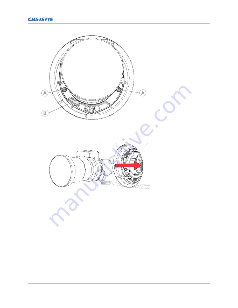
5. Align the lens interface plate with the lens mount and align the lens electrical connector with

the mating connector on the lens mount.

6. Fully insert the assembly straight into the lens mount opening without turning and press with

your hand as shown.

7. To lock the lens assembly in place, while supporting the lens and holding it flat against the lens

mount, push the lens clamp (B in the image in step 4) to lock in position.

8. Remove the front lens cap.
9. To secure the lens to the projector, use a 5 mm hex driver to fasten the security screws (A in

the image in step 4) provided with the lens mount.
Failing to use the security screws leaves the lens loose inside the projector.

Calibrating the lens motor

Ensure the lens motor is calibrated before using the projector.
If the lens motors are not calibrated properly, implications may include:

Incorrect reporting of the lens motor position.

Inability to use the full range of the lens motors.

Lens motors traveling outside of the pre-defined keep-out area.

Installation and setup

Christie M RGB Series Installation and Setup Guide

27

020-103483-04 Rev. 1 (04-2022)

Copyright 

©

 2022 Christie Digital Systems USA, Inc. All rights reserved.

Summary of Contents for M 4K25 RGB

Page 1: ...Installation and Setup Guide 020 103483 04 Christie M RGB Series...

Page 2: ...r warranties or by contacting your Christie dealer or Christie PREVENTATIVE MAINTENANCE Preventative maintenance is an important part of the continued and proper operation of your product Failure to p...

Page 3: ...safety hazards 15 Projector overview 15 Contact your dealer 15 Key features 16 List of components 16 Accessories 16 Technical support 18 Installation and setup 19 Site requirements 19 Power requireme...

Page 4: ...deo Input panel 42 Connecting an HDMI video source 43 HDMI video formats 44 Connecting 12G 6G 3G or HD SDI video source 46 SDI video formats 46 Connecting a DisplayPort video source 54 DisplayPort vid...

Page 5: ...Setting up a single projector to display 3D content 72 Enabling 3D mode 72 Confirming the emitter setup 73 Configuring the projector for the 3D source 73 Connecting devices to the 3D sync ports 73 Re...

Page 6: ...ebsite Read all instructions before using or servicing this product 1 Access the documentation from the Christie website Go to this URL https bit ly 3Af8x7X or https www christiedigital com products p...

Page 7: ...e as specified in this document FIRE HAZARD Keep hands clothes and all combustible material away from the concentrated light beam of the projector Keep fingers and other body parts away from the movin...

Page 8: ...CTRICAL and BURN HAZARD Use caution when accessing internal components Only Christie qualified technicians are authorized to use the tools provided in the toolbox AC power precautions Read all safety...

Page 9: ...ty hazard distance This projector has been classified as Risk Group 3 as per the IEC 62471 5 standard due to possible hazardous optical and thermal radiation being emitted Warning If not avoided the f...

Page 10: ...the Christie projector lens with the zoom adjusted to its most hazardous position Projection Lens Christie M RGB Series effective lens throw Part Number High brightness red line in graph A 0 37 1 ultr...

Page 11: ...tie Ensure the projection system is securely mounted or immobilized to prevent unintended movement or misalignment of the projections A copy of the FDA variance approval letter must be with the operat...

Page 12: ...t the labels that may be used on the product Labels on your product may be yellow or black and white General hazards Hazard warnings also apply to accessories once they are installed in a Christie pro...

Page 13: ...ry Hot surface hazard To avoid personal injury allow the product to cool for the recommended cool down time before touching or handling for maintenance or service Burn hazard To avoid personal injury...

Page 14: ...mber 2018 V 3898 effective on November 21 2018 Indicates a light hazard Do not look directly into the lens The extreme high brightness can cause permanent eye damage Class 1 Laser Product Risk Group 3...

Page 15: ...orm and ultra fast processing of Christie TruLife electronics the Christie M RGB Series is the go to solution for demanding large venue events and applications Contact your dealer Record the informati...

Page 16: ...isting suite of 2K 4K fixed and zoom lenses Full color LCD display to provide information at a glance Integrated keypad control interface Dynamic fan control for quiet operation Field adjustable bores...

Page 17: ...nt Description Part number Air intake filter 6 pack 003 007152 XX Coolant Propylene Glycol 740 003 005179 XX High line operation for 200 240 VAC only line cords Description Part number 250V 10A C13L 3...

Page 18: ...ca 1 800 221 8025 or Support Americas christiedigital com Europe Middle East and Africa 44 0 1189 778111 or Support EMEA christiedigital com Asia Pacific support apac christiedigital com Australia 61...

Page 19: ...provide an airflow 450 cubic feet per minute CFM at 1 to 1000 meters 3 3 to 3280 8 feet elevation and must accommodate a heat load of 3000 W For each additional 1000 meters 3280 8 feet above sea level...

Page 20: ...ses are listed in the Accessories on page 16 topic B Front IR Receives transmissions from the IR remote C Display panel Displays the projector menus and status D Keypad interface Controls the projecto...

Page 21: ...s C Power and Temperature Indicates the light source mode power mode and intake temperature D Status Contains information about the health of the projector including the number of warnings and errors...

Page 22: ...ard the projector s front or rear IR sensor and press a function key One of the two IR sensors on the projector detect the signal and relay the commands for internal processing The remote also offers...

Page 23: ...automatically Q Opens or closes the shutter R Not supported S Initiates a custom action when a number is selected T Selects a projector in multi projector installations U Returns to the previous menu...

Page 24: ...ector Safely lift and position the projector in the location where it will be used Warning If not avoided the following could result in death or serious injury Do not install or operate the projector...

Page 25: ...the image plane Leveling the projector Use the projector feet to level the projector To adjust the vertical position of the projector extend or retract the adjustable feet on the bottom of the projec...

Page 26: ...d affect your displayed image Zoom and Focus Two internal lens motors allow for quick motorized adjustment of zoom and focus Adjust zoom to fit the displayed image on the screen and adjust focus to im...

Page 27: ...ctor use a 5 mm hex driver to fasten the security screws A in the image in step 4 provided with the lens mount Failing to use the security screws leaves the lens loose inside the projector Calibrating...

Page 28: ...ens Use the correct method of removing the lens 1 Remove and retain the two security screws A for installation from the lens mount 2 Rotate the lens clamp B counter clockwise to the open position 3 Sl...

Page 29: ...Standby Light source is off Video electronics are off Projector status is OK Flashing Cool down Projector is moving to one of the two standby states Light source is off and video electronics are booti...

Page 30: ...old the OFF button until you hear a beep When powering off the projector allow the projector to complete its cool down cycle Do not immediately unplug the projector if this can be avoided 2 To turn of...

Page 31: ...eme offset that should be avoided using mechanical alignment 1 Project an image with the primary lens 2 Select a framing test pattern 3 Select LENS OFFSET You can also select MENU Configuration Lens S...

Page 32: ...igh brightness can cause permanent eye damage 1 Close the shutter on the projector 2 Unlock the three lens mount stabilization screws 3 Open the shutter 4 From the Test Pattern menu select the Boresig...

Page 33: ...8 To continue to refine the focus repeat steps 5 to 7 9 Before adjusting the stabilization screws close the shutter 10 To maintain the adjustments lock the stabilization screws When locking the screw...

Page 34: ...ntegrator Rod test pattern 3 Loosen the six screws securing the top cover Two screws are located at the front of the projector and four screws are located at the rear of the projector 4 Slide the top...

Page 35: ...focus Optimize the light focus on the DMDs 1 Set the projector to less than 30 brightness 2 From the Test Pattern menu select the Integrator Rod test pattern 3 Loosen the six screws securing the top c...

Page 36: ...e in step 4 9 Re align or optimize the fold mirror on page 34 10 Replace the top cover Adjusting DMD convergence A convergence problem occurs when one or more projected colors red green and blue appea...

Page 37: ...sults Electronically adjusting convergence with the remote Use the electronic convergence feature with the remote to adjust convergence If warping with Christie Twist or Mystique ensure the warp files...

Page 38: ...the sprite Always align the color components of the sprite to the inner most line color for each axis By default all three color components red green and blue are displayed It may be helpful to obtain...

Page 39: ...onvergence a Save or Discard Changes dialog appears a To save and exit select SAVE and ENTER The convergence settings are applied and saved to the projector before exiting the electronic convergence f...

Page 40: ...1 8th is selected 7 To modify the position for the selected sprite s select Adjust 8 In the ADJUST SPRITE POSITION dialog use the arrow keys to adjust the sprite s position You cannot move the select...

Page 41: ...s in which the projector optimizes video settings for the active signal Auto Setup helps to save time in perfecting a display and you can modify the adjustments as required 1 Make sure of the followin...

Page 42: ...fault and SDVoE The selected option determines what video input configurations are enabled on the Video Input panel To enable the SDVoE option plug in the SDVoE source into the Video Input panel and f...

Page 43: ...3D Sync In 3D Sync Out Supported for 3D enabled projectors J Christie Link Reserved for future use K RS232 Sends receives Christie serial commands using a standard RS232 serial cable L GPIO Provides...

Page 44: ...40 2160 24 25 30 Y CBCR 4 2 2 8 10 12bpc 3840x2160 1 3840 2160 50 60 Y C BC R RGB 4 4 4 8bpc 3840x2160 1 3840 2160 50 60 Y C BC R 4 2 2 8 10 12bpc 4096x2160 1 4096 2160 24 25 30 Y C BC R RGB 4 4 4 8 1...

Page 45: ...50 60 Y C BC R RGB 4 4 4 Y CBCR 4 2 2 8 10 12bpc Frame packing top and bottom 1920x1080 1 1920 1080 24 25 30 50 60 Y C BC R RGB 4 4 4 Y CBCR 4 2 2 8 10 12bpc Frame packing One port dual input 3D The...

Page 46: ...put panel Input configuration Description One Port Enables connection of any of the 12G 6G 3G and HD SDI input standards One Port Dual Input 3D May be used for SDI inputs Four Port Quadrant May be use...

Page 47: ...HD and UHD 4K The following one port 2D HD and UHD 4K image formats are supported on each of the SDI inputs 2048 x 1080 and 4096 x 2160 formats are also supported Format Cables Hres Vres Frame rate Hz...

Page 48: ...T 2081 10 mode 1 structure 1 3840x2160 1 3840 2160 48 50 60 Y C BC R 4 2 2 10bpc 2160p Y C BC R RGB component at 12 0Gb s ST 2082 10 mode 1 structure 1 3840x2160 1 3840 2160 24 25 30 Y C BC R RGB 4 4...

Page 49: ...for input 1 SDI 2 right eye for input1 SDI 3 left eye for input 2 and SDI 4 right eye for input 2 2048 x 1080 and 4096 x 2160 image formats are also supported Format Cables Hres Vres Frame rate Hz Sa...

Page 50: ...1920 1080 48 50 60 Y C BC R 4 2 2 4 12bpc HD 1080p Y C BC R RGB component at 6 0Gb s ST 2081 10 mode 2 structure IV 4K 3840x2160 2 3840 2160 24 25 30 Y C BC R 4 2 2 10bpc 2160p Y C BC R component at...

Page 51: ...Bit depth Notes 4K 3840x2160 4 3840 2160 24 25 30 Y C BC R RGB 4 4 4 4 10bpc Y C BC R RGB component at quad link 3Gb s ST 425 5 level A structure 2 3840x2160 4 3840 2160 24 25 30 Y C BC R RGB 4 4 4 12...

Page 52: ...d link 2D UHD 4K SDI image formats are supported in square division mapping format so each SDI input represents one quarter of the total image assigned as shown in the following diagram Input 1 SDI 1...

Page 53: ...f 2160 image formats B 1 level A mapping 3840x2160 4 3840 2160 24 25 30 Y C BC R 4 2 2 12bpc Y C BC R component at quad link 3Gb s ST 425 5 annex B square division of 2160 image formats B 1 level A ma...

Page 54: ...playPort video source For the projector to accept digital video data plug the DisplayPort source directly into the Video Input panel The input configurations listed below are supported Input configura...

Page 55: ...playPort image formats are supported in a frame sequential transmission format Format Cables Hres Vres Frame rate Hz Sampling Bit depth HD 1280x720 1 1280 720 24 25 30 50 60 Y C BC R RGB 4 4 4 8 10 12...

Page 56: ...ls 0 2047 and DP 2 2058 x 2160 right side pixels 2048 4095 Format Cables Hres Vres Frame rate Hz Sampling Bit depth 4K 1920x2160 per input 2 3840 2160 120 Y C BC R RGB 4 4 4 8 10bpc 2048x2160 per inpu...

Page 57: ...urce directly into the Video Input panel These input configurations are set up on the Christie Link transmitter Refer to the Christie Link User Guide P N 020 102234 XX Christie Link video loop out ena...

Page 58: ...R 4 2 2 8 10 12bpc 12bpc is only applicable to Y C BC R 4 2 2 3840x2160 1 3840 2160 50 60 Y C BC R RGB 4 4 4 Y C BC R 4 2 2 8 10 12bpc 12bpc is only applicable to Y C BC R 4 2 2 4096x2160 1 4096 2160...

Page 59: ...4 8 10bpc One port dual input 3D The following one port dual input 3D image formats are supported where the indicated frame rate is per eye Dual input 3D is a fixed configuration where Input 1 left ey...

Page 60: ...3D frame sequential two column transmission format by Christie Link All frame rates are expressed per eye Format Cables Hres Vres Frame Rate Hz per eye Sampling Bit Depth Notes 4K 1920x2160 per input...

Page 61: ...1 1920 1080 24 25 30 50 60 120 Y C BC R RGB 4 4 4 Y C BC R 4 2 2 8 10 12bpc 2048x1080 1 2048 1080 24 25 30 50 60 120 Y C BC R RGB 4 4 4 Y C BC R 4 2 2 8 10 12bpc 4K 3840x2160 1 3840 2160 24 25 30 50...

Page 62: ...0 50 60 Y C BC R RGB 4 4 4 Y C BC R 4 2 2 8 10 12bpc Frame packing Connecting an HDBaseT video source The HDBaseT port on the Video Input panel accepts digital video data from HDBaseT sources Can conn...

Page 63: ...nnecting to a computer with USB The two USB ports can be used for upgrades backups restores profile management and interrogator retrieval USB C 3 0 Interface USB C Connector with locking mechanism sup...

Page 64: ...r an address You cannot change the IP settings using the web interface 1 From the display panel use the arrow keys to select IP Settings 2 To set the type of network select DHCP or Static 3 If you sel...

Page 65: ...enable the Art Net functionality select Enter Art Net channel listing There are 512 channels per universe Christie M RGB Series specifies 24 channels Christie M RGB Series has multiple methods of bein...

Page 66: ...channel to the projector 10 Lens Horizontal Position Fine 11 Lens Vertical Position Coarse 0 Full lower position 0 255 Full upper position 100 128 Locked by the Lens Shift Enable channel A 250 ms del...

Page 67: ...flexible method of interfacing with external devices to the projector The GPIO is configured to automate real time events Each of the seven pins is defined as either an input or output depending on t...

Page 68: ...3 GPIO 4 Pin 4 GPIO 6 Pin 5 Ground Pin 6 GPIO 1 5V 75mA max e fused to prevent damage Pin 7 GPIO 3 Pin 8 GPIO 5 Pin 9 GPIO 7 All GPIO pins are weakly pulled up to 3 3V Enabling the wired remote keypa...

Page 69: ...the list of port configurations until you find the selection that best matches your configuration The range of available configuration depends on the projector model and or input output combinations W...

Page 70: ...uration is selected the following inputs are supported for each configuration One port HDMI SDI DisplayPort Christie Link HDBaseT Two port DisplayPort Christie Link Four port quadrants SDI One port du...

Page 71: ...tereo 3D applications Christie M RGB Series projector with a Mirage license 3D stereo sync cable for direct input 3D and frame doubled A source usually a computer with a 3D graphics card s Emitter for...

Page 72: ...s one cable supplying the entire frame Dual input 3D In this configuration two video streams are provided by the video server with the left eye supplied by one stream and the right eye supplied by the...

Page 73: ...t 11 Adjust the slider or enter the delay value 12 To confirm your selection select Enter Configuring the projector for the 3D source Configure the projector for the 3D source 1 Select the appropriate...

Page 74: ...ogy equipment Part 1 Safety requirements IEC 62368 1 2014 Audio Video Information And Communication Technology Equipment Part 1 Safety Requirements EN 62368 1 2014 Audio Video IT Communication Technol...

Page 75: ...cable official amendment s Regulation EC No 1907 2006 on the registration evaluation authorization and restriction of chemicals REACH and the applicable official amendment s China Ministry of Informat...

Page 76: ......

Reviews: