27
Chloride Active
UK
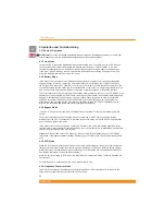
BP-A1000/1500-RT:
1. Battery pack connector
2. RJ11 port for battery pack detection
cable
3. Battery pack connector
4. Circuit breaker
BP-A2000/3000-RT
1. Battery pack connector
2. RJ11 port for battery pack detection
cable
3. Battery pack connector
4. Circuit breaker
4.4 Commissioning and Shutdown
4.4.1 Electrical preparations
WARNING:
Before connecting any input wiring to the UPS, take precautions to ensure that all circuits being
used are the proper voltage and current required for the UPS.
WARNING:
as soon as the UPS is connected to the AC mains supply, voltage is available at the output
sockets (via internal bypass), even if the inverter ON button has not been pressed. When this button is
pressed, the inverter is switched on and the UPS starts working in line mode.
WARNING:
Electrical shock hazard: even when the UPS is disconnected from the mains, hazardous
voltages may still exist at the output receptacles of the UPS. The UPS receives power from more than
one source – AC input and DC input from batteries. All input sources (AC and DC) must, therefore, be
disconnected before carrying out maintenance work inside the UPS.
NOTE:
Under EMC regulations, output cables can not be longer than 10 meters, communication cables can
not be longer than 3 meters and battery extension cables can not be longer than 3 meters.
4.4.2 Connections
4.4.2.1 External battery packs connections
WARNING:
Before connecting a battery pack to the UPS, the circuit breaker of the battery pack must be
switched to “OFF”. After electrical connection with the UPS is established, the breaker must be switched to
“ON”.
NOTE:
Each battery pack contains two battery connectors. The rst battery pack is connected to the UPS
using the cable supplied with the pack. Each additional extension battery pack is connected by attaching its
cable to the previous pack.
If external battery packs are to be used, they should be connected prior to connection the UPS to the input
power. To connect external battery cabinets, follow the steps below:
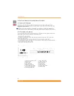
1. Set the circuit breaker on each battery cabinet to the “OFF” position
2. Connect a battery extension cable between the battery receptacle on the rear of the UPS and one
battery receptacle on the rear of the rst battery pack
3. Connect a battery extension cable between one battery receptacle on the rear of the rst battery pack


