www.chipsee.com
www.chipsee.com
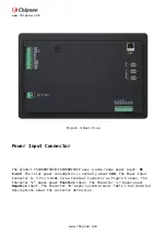
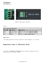
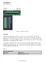
Figure 5 Power Input Connector
Table 1
Power Input Pin Definition:
Pin Number
Definition
Description
Pin 1
Positive Input
Connect to DC Power Positive Terminal
Pin 2
Negative Input
Connect to DC Power Negative Terminal
Pin 3
Ground
Connect to Power System Ground
Please note:
The system ground “G” has been connected to power Negative “–” on board.
Capacitive Touch or Resistive Touch
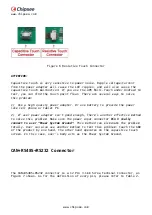
The product CS10600T101E/CS10600T101P uses 10-point capacitive touch or
resistive touch, as Figure 6 shows.
Summary of Contents for CS10600T101E
Page 1: ...www chipsee com www chipsee com EPC PPC A8 101 R User Manual Release 1 0...
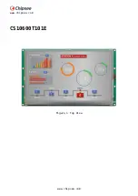
Page 5: ...www chipsee com www chipsee com CS10600T101E Figure 1 Top View...
Page 6: ...www chipsee com www chipsee com Figure 2 Back View CS10600T101P...
Page 7: ...www chipsee com www chipsee com Figure 3 Top View...
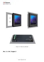
Page 23: ...www chipsee com www chipsee com Figure 19 Mounting Method How to Get Support...

