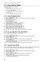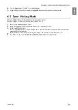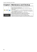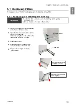
Chapter 6
Useful Utilization (Optional)
CMN209-004
59
E
ng
lis
h
Chapter 6
Useful Utilization (Optional)
6.1
Remote Cable
6.1.1
Electrical Diagram
■
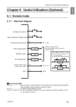
Remote operation
Pin
④
.........................
When turned on, control switches to the remote mode, enabling remote operation
while disabling ordinary
operation via the AT3 panel.
Pin
②
.........................
Outputs an analog pressure signal.
Pins
③
,
⑤
, and
⑥
...
In case of adding an inductor (e.g., relay), install a noise limiter (approx. 33 Ω +
0.1 μF), diode, or the like.
Operation input signal
Remote operation change signal
Operating pressure signal
Filter clogging signal
Operation signal
Abnormality signal
GND
④
⑤
⑦
③
②
⑧
⑥
DC
1
~
5V
When adding an inductor (e.g., relay),
attach a noise limiter (approx. 33
Ω
+
0.1
μ
F) ,to the output
terminal(terminal numbers
③⑤
and
⑥
).
LOAD
LOAD
DC
0
~
5V
GND
①
LOAD
LOAD
LOAD
Suction power level
change input signal
Withstand voltage 50 Vdc.
Also,use the inductor with a current of
less than 100mA
Summary of Contents for CMP-2500AT3-A
Page 3: ......
Page 7: ...1 CMN209 006 3 1 1 1 1 2 10 60 80 1 3 0 40 80 100 1 000...
Page 8: ...1 4 1 4 2 OFF NV63 SVF 3P 30A 1 5...
Page 10: ...2 6 2 2 1 4 HEPA V1 1 1 1 1 AWG14 2 08...
Page 11: ...2 CMN209 006 7 2 2 2 2 1 CMP 2500 AT3 A V1 AT3 BOX HEPA V1...
Page 14: ...2 10 2 4 3 OP kPa SP kPa DP kPa EP kPa Blower Motor rpm Runtime h 17 Total h...
Page 15: ...3 CMN209 006 11 3 3 1 3 1 1 0 40 80 RH...
Page 16: ...3 12 3 1 2 200 230V 1 BOX 2 3...
Page 17: ...3 CMN209 006 13 1 2 8 3 2 1 RS485 ID 2 AT3 ON 3 4 1 7 3 ON OFF 3 30 ON OFF Ver ID...
Page 23: ...5 CMN209 006 19 5 OFF 2...
Page 24: ...5 20 5 1 WARN2 1 5 1 1 1 1 2 2 3 4 5 2...
Page 25: ...5 CMN209 006 21 5 1 2 1 1 1 2 2 2 3 4 1 5 6 2...
Page 26: ...5 22 5 1 3 V1 1 4 2 3 4 5 2 1 1 1 1...
Page 29: ...5 CMN209 006 25 5 4 EL 1 2 3 4 1 4 30 1 1 5 1 20 5 1 20 5 1 20 5 1 20...
Page 31: ...6 CMN209 006 27 1 5V 0 2V B C ON HIGH LOW OFF LOW HI Z LOW DC 1 2...
Page 35: ...7 CMN209 006 31 7 3 7 3 1 CMP 2500AT3 A...
Page 36: ...32 12 7 2 7 2 30...
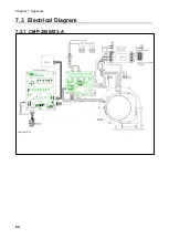
Page 68: ...Chapter 7 Appendix 64 7 3 Electrical Diagram 7 3 1 CMP 2500AT3 A Internal terminal...

