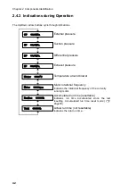
Chapter 4
Various settings (mode select mode)
50
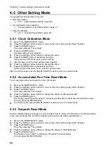
4.5
Other Setting Mode
The parameters listed below can be set.
•
Date/time setting
Clock Calibration Mode” (page 50)
•
Accumulated run time resetting
“Accumulated Run Time Reset Mode
“(
page 17
)
•
Setpoint resetting
Setpoint Reset Mode” (page 50)
4.5.1
Clock Calibration Mode
1.
Move to the MODE SELECT mode.
2.
Press the Up/Down arrow buttons to move to the other setting mode (“Other Setting”).
3.
Press the ENTER button.
The screen displays “Time Adjust”.
4.
Press the ENTER button.
The date setting screen appears.
5.
Press the Up/Down arrow buttons to change the value.
6.
Press the ENTER button to determine the value.
Set the value in this order: year, month, and day.
7.
After the date is set, the time setting screen appears.
8.
Press the Up/Down arrow buttons to change the value.
9.
Press the ENTER button to determine the value.
Set the value in this order: hours, minutes, and seconds.
10.
To exit this mode, press the MODE SELECT button to return to normal mode.
4.5.2
Accumulated Run Time Reset Mode
This mode resets the accumulated run time (“Runtime”).
1.
Move to the MODE SELECT mode.
2.
Press the Up/Down arrow buttons to move to the other setting mode (“Other Setting”).
3.
Press the ENTER button.
The screen displays “Time Adjust”.
4.
Press the Up/Down arrow buttons to change the display to “[Runtime Reset]”.
5.
Press the ENTER button.
The display shows “Reset Runtime Y”, prompting confirmation to reset the accumulated run time.
To reset, press the ENTER button.
6.
To exit this mode, press the MODE SELECT button to return to normal mode.
4.5.3
Setpoint Reset Mode
Restore standard factory settings for communication format, timing of notification of insufficient airflow,
pulse control interval time and AUTO setting, and reset the cumulative operating time.
1.
Move to the MODE SELECT mode.
2.
Press the Up/Down arrow buttons to move to the other setting mode (“Other Setting”).
3.
Press the ENTER button.
The screen displays “Time Adjust”.
4.
Press the Up/Down arrow buttons to change the display to “[Setting Reset]”.
5.
Press the ENTER button.
The display shows “1
:
YES”, prompting confirmation to reset setpoints.
To reset, press the ENTER button.
Summary of Contents for CMP-2500AT3-A
Page 3: ......
Page 7: ...1 CMN209 006 3 1 1 1 1 2 10 60 80 1 3 0 40 80 100 1 000...
Page 8: ...1 4 1 4 2 OFF NV63 SVF 3P 30A 1 5...
Page 10: ...2 6 2 2 1 4 HEPA V1 1 1 1 1 AWG14 2 08...
Page 11: ...2 CMN209 006 7 2 2 2 2 1 CMP 2500 AT3 A V1 AT3 BOX HEPA V1...
Page 14: ...2 10 2 4 3 OP kPa SP kPa DP kPa EP kPa Blower Motor rpm Runtime h 17 Total h...
Page 15: ...3 CMN209 006 11 3 3 1 3 1 1 0 40 80 RH...
Page 16: ...3 12 3 1 2 200 230V 1 BOX 2 3...
Page 17: ...3 CMN209 006 13 1 2 8 3 2 1 RS485 ID 2 AT3 ON 3 4 1 7 3 ON OFF 3 30 ON OFF Ver ID...
Page 23: ...5 CMN209 006 19 5 OFF 2...
Page 24: ...5 20 5 1 WARN2 1 5 1 1 1 1 2 2 3 4 5 2...
Page 25: ...5 CMN209 006 21 5 1 2 1 1 1 2 2 2 3 4 1 5 6 2...
Page 26: ...5 22 5 1 3 V1 1 4 2 3 4 5 2 1 1 1 1...
Page 29: ...5 CMN209 006 25 5 4 EL 1 2 3 4 1 4 30 1 1 5 1 20 5 1 20 5 1 20 5 1 20...
Page 31: ...6 CMN209 006 27 1 5V 0 2V B C ON HIGH LOW OFF LOW HI Z LOW DC 1 2...
Page 35: ...7 CMN209 006 31 7 3 7 3 1 CMP 2500AT3 A...
Page 36: ...32 12 7 2 7 2 30...
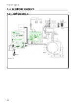
Page 68: ...Chapter 7 Appendix 64 7 3 Electrical Diagram 7 3 1 CMP 2500AT3 A Internal terminal...

