Chapter 2 Components Identification
38
2.3
AT3 Panel
No.
Name
Function
①
Organic EL
(OLED) display
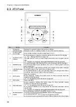
Displays the operating status and various settings.
Displays an error or warning number in case of an error or warning.
②
Suction power
level lamps
Green lamps indicate a suction power level (1 to 7).
③
Up/Down arrow
buttons
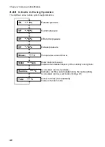
During stoppage or operation, switches among the content of the display.
Display Indications” (page 39)
In MODE SELECT mode
, cycles through parameters and changes numeric
data.
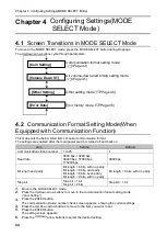
“Chapter 4 Configuring Settings(MODE SELECT Mode)(page44)
④
ERROR lamp
The red lamp lights upon detection of an error that stops device operation.
The red lamp flickers upon detection of an error or warning that continues
device operation.
⑤
Left/Right arrow
buttons
During operation, each pressing of the
Left (or Right) arrow button
changes
the suction power to the next lower (or higher) level.
During MODE SELECT mode
, each pressing of the
Left (or Right) arrow button
moves the cursor left (or right) to the next position.
⑥
OFF button
Stops the operation.
During stoppage, holding this button down for three seconds clears the
registered initial pressure.
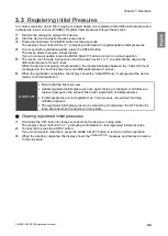
Registering Initial Pressures“ (page 43)
⑦
ON button
Starts operation.
⑧
ENTER button
During operation, holding this button down for three seconds causes
transition to initial pressure registration.
Registering Initial Pressures“ (page 43)
During SELECT MODE mode
, determines the selected parameter and its
numeric data.
“Chapter 4 Configuring Settings(MODE SELECT Mode)(page44)
⑨
MODE SELECT
button
During stoppage, transits to
the MODE SELECT mode
.
“Chapter 4 Configuring Settings(MODE SELECT Mode)(page44)
During MODE SELECT mode
, returns to the previous mode.
During an error/warning
, transits to the error history mode or error clear mode.
l
①
②
④
⑥
③
③
⑤
⑦
⑤
⑨
⑧

