background image

WM210-220-230-240S/SI

Installation Instructions

6

SITE REQUIREMENTS (WM2XXS

I

 and WM2XXS Models) - Steel Stud Structure
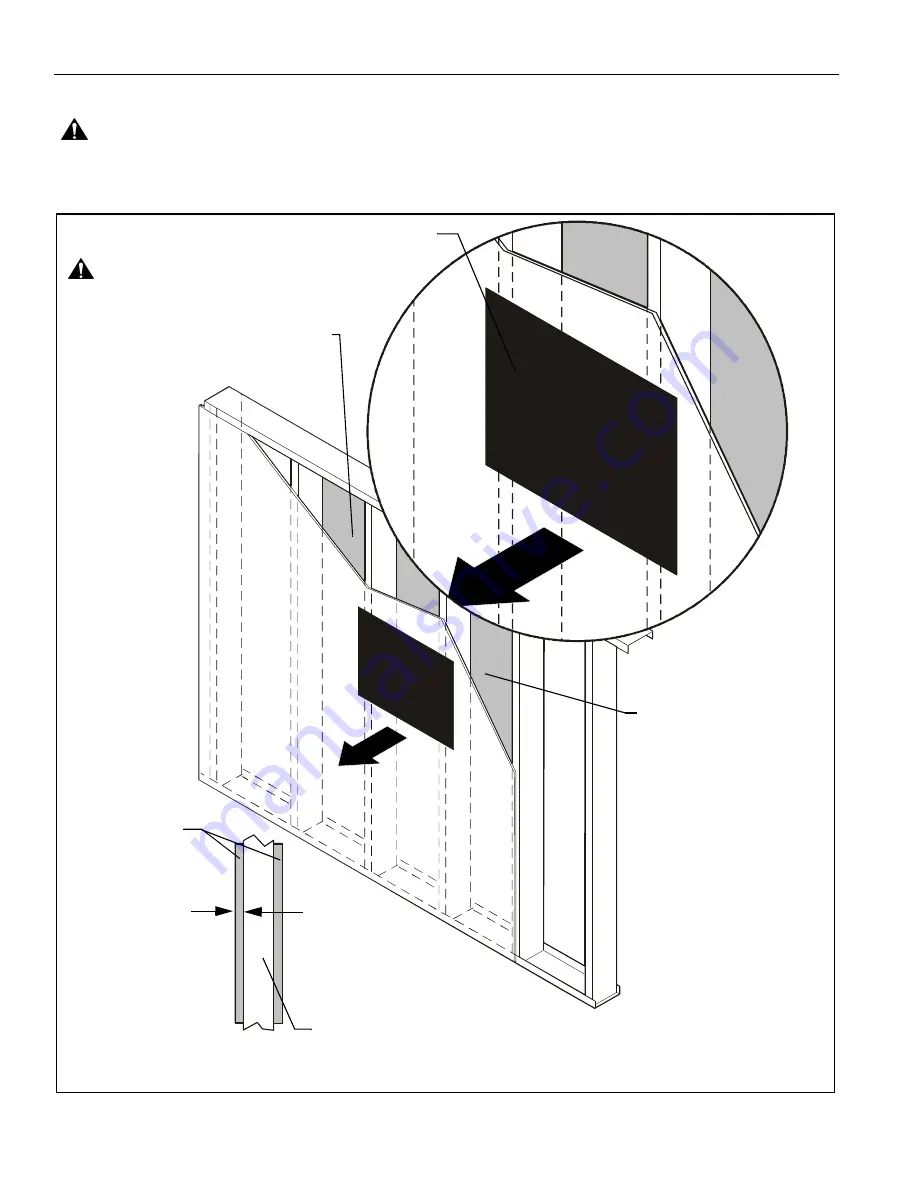
WARNING:

IMPROPER INSTALLATION CAN LEAD TO EQUIPMENT FALLING CAUSING SERIOUS PERSONAL INJURY

OR DAMAGE TO EQUIPMENT!  The figure below identifies the minimum requirements for installation of display mounts onto a
steel stud structure. If the structure or its components do not meet these requirements contact the mount manufacturer for specific
instructions before attempting installation. It should also be noted that no other equipment should be mounted to the same stud.
(See Figure 1)

Figure 1

(Must be centered on stud)

Drywall

**1/2" minimum

Drywall Thickness

Display Mount Installation Location

FRONT

(Both Sides of Stud)

There must be a minimum of
1-7/8" (48mm) clearance
inside wall

16" or 24" (on center) Studs

If back side of wall is unfinished, drywall must be installed
to a minimum of one stud left and right of the stud(s)
being used to install the mount. Drywall must be
secured to studs with screws 12" on center

Steel Stud (2 x 4 / 25ga minimum)
Stud type and structural strength must conform to the North American
Specification for the Design of Cold-Formed Steel Structural Members.

**See hazard statement

on page 2!

[362, 125 18, C-Shape, S - Stud Section]

Summary of Contents for WM210S

Page 1: ...ni di installazione Installatie instructies Instructions d installation WM 210SI WM 220SI WM 230SI WM 240SI Dual Stud Short Throw Wall Mounts Spanish Product Description German Product Description Por...

Page 2: ...dequate structural strength for this component can result in serious personal injury or damage to equipment It is the installer s responsibility to make sure the structure to which this component is a...

Page 3: ...63 1 42 1 09 CABLE CHANNEL DIMENSIONS THRU ARM DIMENSIONS INCHES WM2XXS Standard Model 10 81 274 64 7 25 184 14 75 19 06 16 00 406 40 11 53 292 85 34 8 69 210SI TRAVEL 12 75 19 5 240SI TRAVEL 37 2 65...

Page 4: ...schl ssel Chave de bocas Chiave a punte aperte Steeksleutel Cl fourche By Hand A mano Von Hand Com a m o A mano Met de hand la main Hex Head Wrench Llave de cabeza hexagonal Sechskantschl ssel Chave d...

Page 5: ...rity top cap bottom cap WM 210 WM 230 WM 240 Q 4 1 4 R 1 3 16 concrete anchor X 1 Cover top Y 1 Interactive cover AC 1 Interactive software AD 1 AAA battery AH 1 Interactive A 1 Short throw wall mount...

Page 6: ...at no other equipment should be mounted to the same stud See Figure 1 Figure 1 Must be centered on stud Drywall 1 2 minimum Drywall Thickness Display Mount Installation Location FRONT Both Sides of St...

Page 7: ...hard drive space Available USB port Macintosh System Power PC Intel 1 42 GHz processor and 1G RAM Mac OS X 10 5 through 10 6 25 MB available hard drive space Available USB port Active Capture Area Siz...

Page 8: ...ld be positioned within the fan area extending from the Chief Interactive Dual Mount This fan area should not exceed 140 degrees Whiteboard Constraints The whiteboard should not be thicker than 1 See...

Page 9: ...or Concrete Block 1 Determine mounting location on wall 2 Using wall bracket B as a template mark four holes at the holes in bracket See Figure 4 3 Drill four 3 8 holes at marked locations in wall Se...

Page 10: ...nner four holes in bracket See Figure 8 4 Drill four 1 2 holes at marked locations in wall See Figure 8 Figure 8 5 Hold metal channel on anchor P flat alongside plastic straps and slide channel throug...

Page 11: ...SERIOUS PERSONAL INJURY OR DAMAGE TO EQUIPMENT Overtightening of mounting hardware can damage the steel studs DO NOT overtighten mounting hardware Figure 12 Installation to Wall Bracket 1 Lift short t...

Page 12: ...for the WM230S SI or WM240S SI NOTE RPM RPA and RSA are sold separately Figure 17 NOTE Determine hole configuration to use for each specific projector mount See Figure 17 RPM Installation 1 Line up mo...

Page 13: ...screws S through RSA holes and into projector mounting plate See Figure 21 Figure 21 3 Install interface and projector to RSA according to RSA installation instructions WM2XXSI INTERACTIVE MOUNT Insta...

Page 14: ...mount But for some thick cables removing the covers may be necessary Removing Mount Covers 1 Remove and save two 8 32 x 3 8 Phillips pan head screws AB from upper cover See Figure 25 2 Raise and remo...

Page 15: ...hannel and into opened cable clips See Figure 29 Proceed to Step 9 Figure 29 Routing Cables from Above Step 8 8 Thread cables down through a surface mount cable accessory not included then behind and...

Page 16: ...be used use the security screws V to install wall bracket covers See Security Screw Installation section for details 1 Place wall bracket top caps C over top of each wall bracket arm See Figure 34 Fi...

Page 17: ...de of pitch adjustment screw See Figure 38 3 Adjust pitch adjustment screw until mount is at desired pitch level Turn clockwise to raise mounting level or turn counterclockwise to lower mounting level...

Page 18: ...igure 40 Figure 40 4 Return outer covers to the mount following instructions in Installing Mount Covers section Security Screw Installation Optional Wall Bracket Covers 1 Remove eight 8 32 x 1 2 Phill...

Page 19: ...head security screws AA into lower cover See Figure 45 Figure 45 5 Replace upper cover and install two 8 32 x 3 8 button head security screws AA into upper cover See Figure 46 Figure 46 Stop Bracket...

Page 20: ...ommended to remove projector prior to performing the following steps WARNING It is important to replace adapter plate bolts ONE AT A TIME or adapter plate could fall from mount during installation 2 R...

Page 21: ...lips pan head screws F See Figure 52 Figure 52 Cable Management Optional In most cases cable management covers will NOT need to be removed in order to route cables from projector to the wall mount But...

Page 22: ...ips along bottom edge of wall bracket See Figure 56 Figure 56 6 Thread cable up wall bracket channel and into opened cable clips See Figure 57 Proceed to Step 8 Figure 57 Routing Cables from Above Ste...

Page 23: ...outer covers to the mount following instructions in Installing Mount Covers section Installation of Wall Bracket Covers NOTE If security screws are going to be used use the security screws V to insta...

Page 24: ...f mounting bracket See Figure 65 Figure 65 2 Loosen two bolts on either side of pitch adjustment screw See Figure 66 3 Adjust pitch adjustment screw until mount is at desired pitch level Turn clockwis...

Page 25: ...sition See Figure 68 3 Tighten two 1 4 20 x 5 8 hex head cap screws E loosened in Step 1 See Figure 68 Figure 68 4 Return outer covers to the mount following instructions in Installing Mount Covers se...

Page 26: ...ty screws V into holes on mount cover See Figure 71 Figure 71 Stop Bracket 1 Remove two bolts holding stop bracket in place on underside of short throw projector mount See Figure 72 Figure 72 2 Instal...

Page 27: ...the following steps WARNING It is important to replace adapter plate bolts ONE AT A TIME or adapter plate could fall from mount during installation 2 Remove one of four bolts from adapter plate See F...

Page 28: ...495 580 852 F 31 0 495 580 845 Asia Pacific A Office No 1 on 12 F Shatin Galleria 18 24 Shan Mei Street Fotan Shatin Hong Kong P 852 2145 4099 F 852 2145 4477 WM210 220 230 240S SI Installation Instr...

Reviews: