background image

MSP-WL4C

Installation Instructions

8

4.

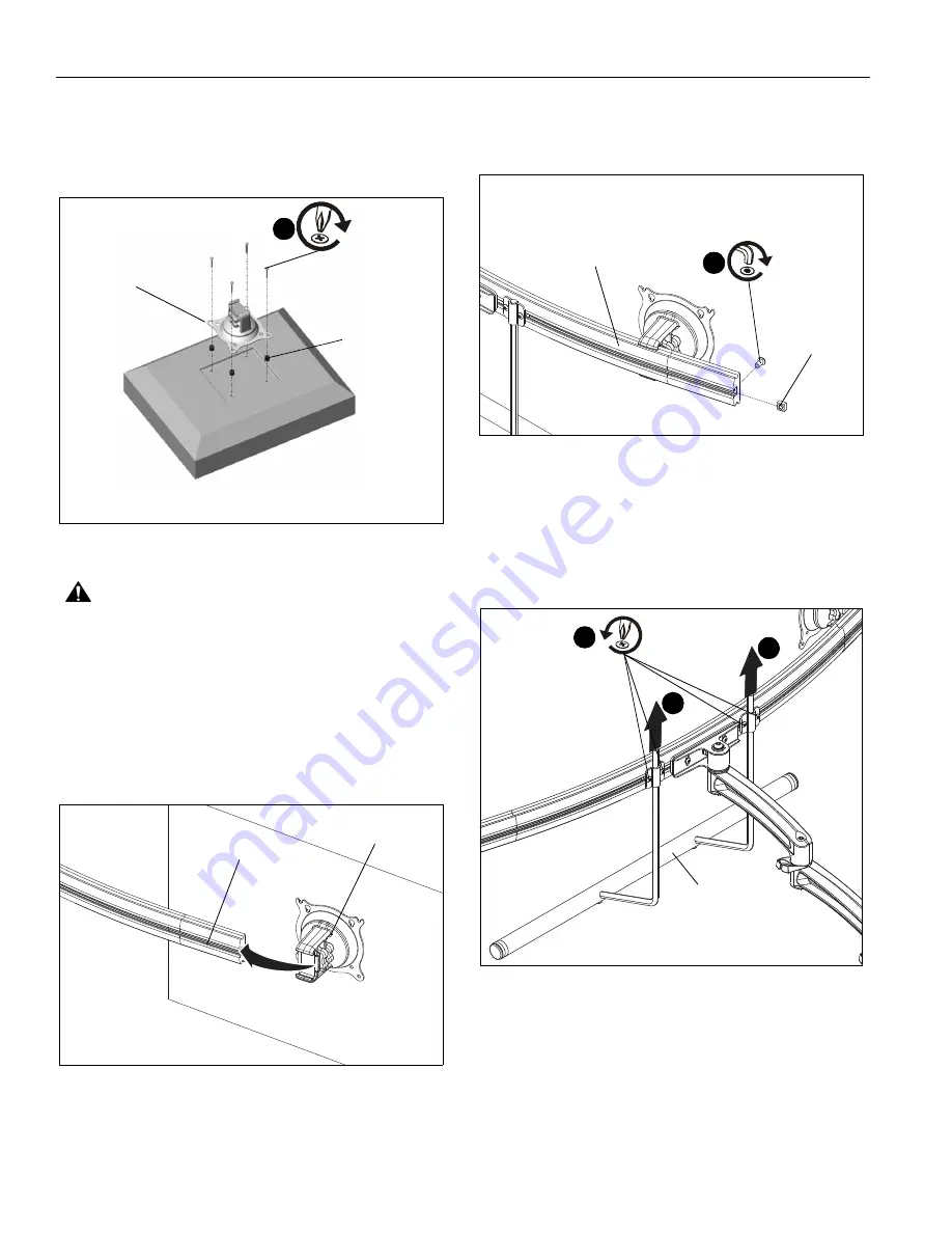
Place the four selected spacers over each of the mount
holes on the back of the display.

5.

Place the Centris head (dual knob assembly) onto the
spacers, aligning the mounting holes on the Centris bracket
with the holes in the spacers. (See Figure 7)

Figure 7

CAUTION:

Using screws of improper size may

damage your display! Proper screws will easily and
completely thread into display mounting holes.

6.

Using Phillips screwdriver, install four selected screws
through the mounting holes in Centris bracket, through the
spacers, into the display (See Figure 7). Tighten all four
screws. Do not overtighten!

7.

Slide the Centris head (dual knob assembly) onto the array
(See Figure 8). Ensure both the top and the bottoms of the
Centris head are engaged into the corresponding slots in
the array (J).

Figure 8

8.

Position the displays as desired and tighten the Centris
head knob closest to the

array

 (J). See "ADJUSTMENT" for

additional information.

9.

Using 5/32" hex key (X), install screw and nut on each end
of the array (J) to prevent displays from accidentally sliding
off. (See Figure 9)

Figure 9

Handle Installation

1.

Loosen four screws securing handle brackets to array. (See
Figure 10)

2.

Install uprights of handle (K) into handle brackets located on
the back of array. (See Figure 10)

Figure 10

(C or D) x 4

(E or F) x 4

Centris
Bracket

6

(J)

Centris Head

(screw)

(nut)

9

(J)

2

2

(K)

1

x 4

Summary of Contents for MSP-WL4C

Page 1: ...ruções de Instalação Istruzioni di installazione Installatie instructies Instructions d installation Office Furniture Array Mount Spanish Product Description German Product Description Portuguese Product Description Italian Product Description Dutch Product Description French Product Description MSP WL4C ...

Page 2: ...o the possibility of damage or destruction of equipment if you do not follow the corresponding instructions IMPORTANT SAFETY INSTRUCTIONS WARNING Failure to read thoroughly understand and follow all instructions can result in serious personal injury damage to equipment or voiding of factory warranty It is the installer s responsibility to make sure all mounting systems are properly assembled and i...

Page 3: ...Installation Instructions MSP WL4C 3 DIMENSIONS 5 3 133 4 MAXIMUM 30 73 780 5 22 53 572 4 ...

Page 4: ...Chave de bocas Chiave a punte aperte Steeksleutel Clé à fourche By Hand A mano Von Hand Com a mão A mano Met de hand À la main Hex Head Wrench Llave de cabeza hexagonal Sechskantschlüssel Chave de cabeça sextavada Chiave esagonale Zeskantsleutel Clé à tête hexagonale Pencil Mark Marcar con lápiz Stiftmarkierung Marcar com lápis Segno a matita Potloodmerkteken Marquage au crayon Drill Hole Perforar...

Page 5: ... B 8 M4x12mm C 8 M4x20mm D 8 M4x30mm 3 16 1 8 W 1 Y 1 J 1 Array K 1 Handle P 1 5 16 18 x 3 1 8 L 1 Pivot pin Q 1 Pocket washer H 1 5 16 18 R 2 Array Cable T 2 Thin steel U 1 Plastic V 1 Rotational spacer washer washer clip M 1 Cable clip N 1 Pivot point spacer G 10 Cable tie Hardware bag E 8 3 4 F 8 3 8 S 2 Stainless steel washer X 1 5 32 ...

Page 6: ... Using 1 2 socket tighten tension hex head bolt until lower mounting plate slides into channel in wall and continue tightening until resistance is felt See Figure 2 Figure 2 5 Tighten two upper and lower button head cap screws to secure OFBU bracket to wall See Figure 3 Figure 3 IMPORTANT If the display being installed has a recessed mounting surface the display must be assembled to the mount prio...

Page 7: ...e of the mount and its accessories causing possible injury 3 Carefully place display face down on protective surface 4 Place the Centris head dual knob assembly onto the back of the display aligning the mounting holes on the Centris bracket with the mounting holes on the display CAUTION Using screws of improper size may damage your display Proper screws will easily and completely thread into displ...

Page 8: ...ghten all four screws Do not overtighten 7 Slide the Centris head dual knob assembly onto the array See Figure 8 Ensure both the top and the bottoms of the Centris head are engaged into the corresponding slots in the array J Figure 8 8 Position the displays as desired and tighten the Centris head knob closest to the array J See ADJUSTMENT for additional information 9 Using 5 32 hex key X install s...

Page 9: ...isplay to desired position See Figure 12 Using your fingers tighten adjustment knob A Figure 12 2 PITCH YAW ROLL Using your fingers slightly loosen adjustment knob B See Figure 12 Adjust display as desired Using your fingers tighten adjustment knob B Array Bar Roll Adjustment 1 Loosen roll adjustment screws on back of array bracket See Figure 13 2 Adjust roll of array bar as desired See Figure 13 ...

Page 10: ...MSP WL4C Installation Instructions 10 ...

Page 11: ...Installation Instructions MSP WL4C 11 ...

Page 12: ...3 DK Weert Netherlands P 31 0 495 580 852 F 31 0 495 580 845 Asia Pacific A Office No 918 on 9 F Shatin Galleria 18 24 Shan Mei Street Fotan Shatin Hong Kong P 852 2145 4099 F 852 2145 4477 MSP WL4C Installation Instructions Chief a products division of Milestone AV Technologies 8800 002804 Rev00 2017 Milestone AV Technologies www milestone com 03 17 ...

Reviews: