Installation Instructions
MSP-WLB/D SERIES
7
IMPORTANT ! :
If the display being installed has a recessed
mounting surface, the display must be assembled to the mount
prior to mount installation. See
Display Installation
in this
document before proceeding.
6.
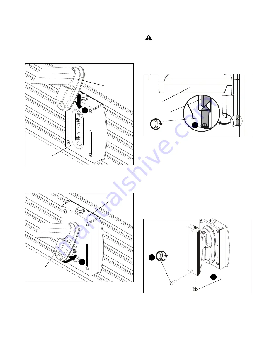
Insert top of mount (D or F) over lip on top of wall bracket
(V). (See Figure 4)
Figure 4
7.
Swing mount (D or F) down flush against wall bracket (V).
(See Figure 5)
Figure 5
8.
Tighten set screw using 5/32” hex key (EE). (See Figure 6)
CAUTION:
IMPROPER INSTALLATION CAN LEAD TO
DISPLAY FALLING CAUSING SERIOUS PERSONAL
INJURY OR DAMAGE TO EQUIPMENT! Make sure set
screw engages back side of mounting dish on wall bracket
(V). (See Figure 6)
Figure 6
Centris Head to Array (WL2B and WL3B only)
IMPORTANT ! :
If you will be installing a display with
RECESSED mounting holes, then proceed to
Display
Installation
section
before continuing
with this mount
installation procedure.
1.
Install 1/4-20” square nut (K) into back groove of vertical
array (D or Y) and line up with bottom hole on plate. (See
Figure 7)
2.
Install 1/4-20 x 1/2” button head cap screw (J) into lower
hole on vertical array (D or Y) and through square nut (K).
(See Figure 7)
Figure 7
(V)
(D or F)
6
(V)
(D or F)
7
(V)
(D or F)
8
(J)
(K)
1
2
(MSP-WL3B shown)


