MSP-WLB/D SERIES
Installation Instructions
18
WL6B
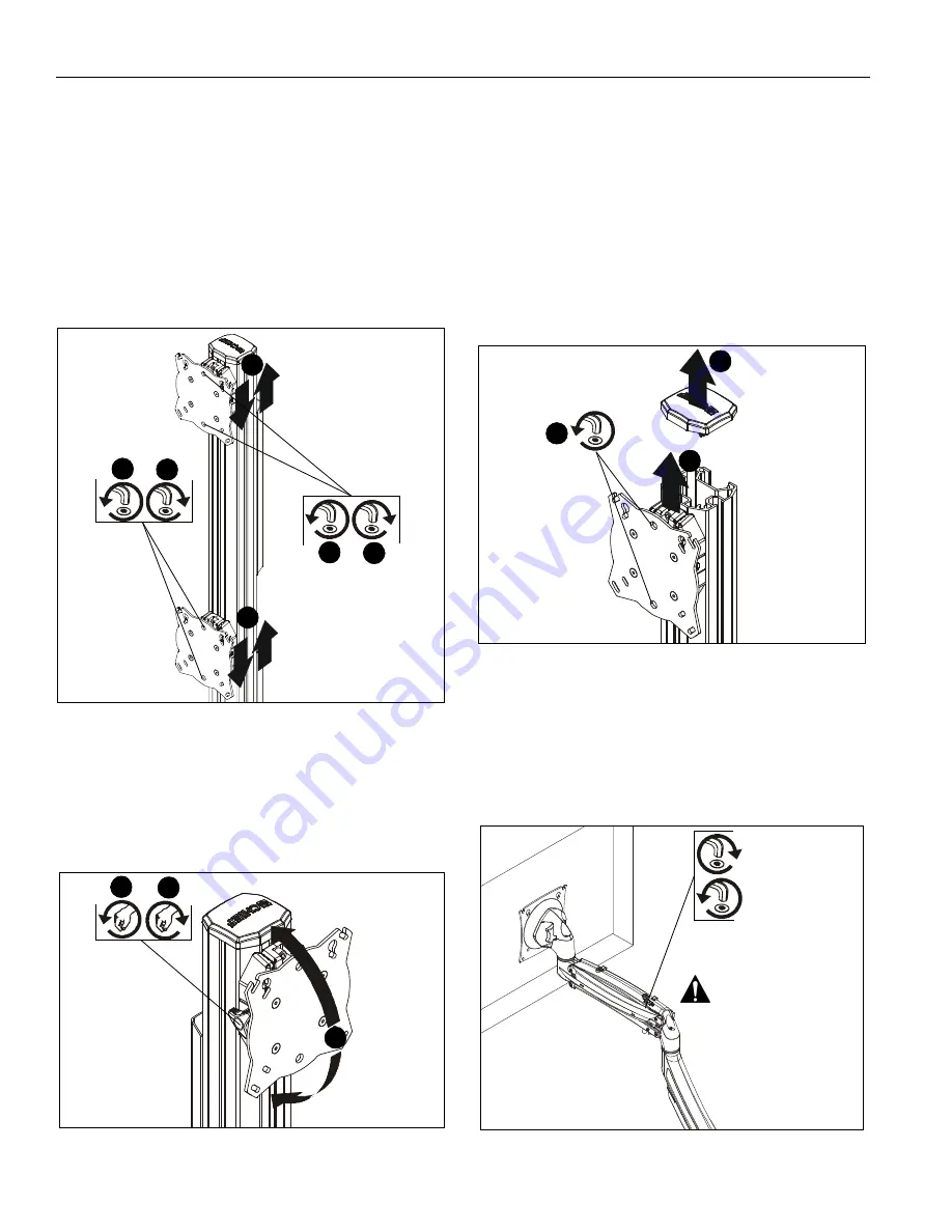
Height Adjustment
NOTE:
Height adjustment should be set prior to installing
display. Due to the location of the height adjustment
screws, the displays will need to be removed in order to
adjust the height. (See Figure 43)
1.
Loosen height adjustment screws for specific display that
will be adjusted. (See Figure 43)
2.
Adjust arm or display to desired height. (See Figure 43)
3.
Tighten height adjustment screws to lock display’s position.
(See Figure 43)
Figure 43
Pitch
1.
Loosen knob on side of center faceplate assembly. (See
Figure 44)
2.
Adjust pitch as desired. (See Figure 44)
3.
Tighten knob to secure desired pitch position. (See Figure
44)
Figure 44
Roll
1.
Loosen screws holding display to faceplate slightly.
2.
Adjust roll position as the mounting holes on faceplate
allow.
3.
Tighten screws to lock roll position.
Faceplate Assembly Removal
1.
Remove column cap (M) from array column. (See Figure
45)
2.
Loosen height adjustment screws for center faceplate
assembly. (See Figure 45)
3.
Slide faceplate assembly up through column channel until it
is removed from column. (See Figure 45)
Figure 45
WL9D, WL10D, WL11D, WL12D and WL13D
Lift Arm Tension Adjustment
1.
Tension may be adjusted with tension adjustment screw
inside cable management cover and 1/8” hex key (FF). Turn
clockwise to reduce tension or counter-clockwise to
increase tension. (See Figure 46)
Figure 46
2
2
1
3
1
3
1
3
2
2
3
1
Reduce tension
Increase tension
(lighter display)
(heavier display)
Do NOT over-tension
adjustment tension
screw.


