background image

SKU 46507

PAGE 9

1.

Caution:  Check to make sure the Switch (part #33) is in its “OFF” position before
plugging the Power Cord (part #36) into a 110-120 Volt, grounded,
electrical power outlet.  (See Figures B, C, and Assy. Diagram.)

2.

Make sure to use both hands to 

firmly grip the Polisher/Sander by its Side

Handle (part #20) and Back Handle (part #39).  (See Figures B, C, and Assy.
Diagram.)

3.

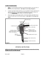
To turn on the Polisher/Sander, squeeze the Switch (part #33).  To turn off the
Polisher/Sander, release pressure on the Switch.  NOTE:  For automatic, continu-
ous running, squeeze the Switch while, at the same time, depressing the Switch
Lock.  This locks the Switch in its “ON” position.  To turn off the Polisher/Sander,
squeeze and quickly release pressure on the Switch.  This unlocks the Switch,
and allows the Polisher/Sander to automatically turn off.  (See Figures B, C, and
Assy. Diagram.)

4.

Allow the Polisher/Sander to spin up to full speed before pressing it onto the
workpiece.  (See Figures B, C, and Assy. Diagram.)

5.

NOTE:  The Polisher/Sander can be operated at different speeds (from 1,000
RPM to up to 3,000 RPM), depending on the material of the workpiece.  To
change speeds, 

make sure the Polisher/Sander is off.  Then, select the desired

speed, using the Variable Switch (part #31).  (See Figures B, C, and Assy.
Diagram.)

6.

Do not force the Polisher/Sander onto the workpiece.  Apply moderate pressure,
allowing the Polisher/Sander to do the work without being forced.  (See Figures
B, C, and Assy. Diagram.)

7.

Move the Polisher/Sander along the workpiece in small, circular, patterns.  (See
Figures B, C, and Assy. Diagram.)

8.

When finished, turn off the Polisher/Sander and allow the Polishing Disc or the
Rubber Backing Plate to spin down and stop on their own.  Do not press against
the disc to stop them.  (See Figures B, C, and Assy. Diagram.)

INSPECTION, MAINTENANCE, AND CLEANING

1.

Caution:  Always disconnect the Polisher/Sander from its electrical power supply
source before performing any inspection, maintenance, or cleaning.

2.

Before each use, inspect the general condition of the Polisher/Sander.  Inspect
switch, power plug and cord assembly, and extension cord (if used) for damage.
Check for loose screws, misalignment, binding of moving parts, broken, cracked,
or improper mounting of the Polishing Disc or the Rubber Backing Plate, broken

Summary of Contents for CHICAGO 46507

Page 1: ...t our Web site at http www harborfreight com Copyright 2001 by Harbor Freight Tools All rights reserved No portion of this manual or any artwork contained herein may be reproduced in any shape or form...

Page 2: ...equipment and keep out of reach of children 4 DO NOT USE THIS PRODUCT IF UNDER THE INFLUENCE OF ALCOHOL OR DRUGS Read warning labels on prescriptions to determine if your judgment or reflexes are imp...

Page 3: ...y identical replacement parts Only use accessories intended for use with this product Approved accessories are available from Harbor Freight Tools 12 MAINTAIN THIS PRODUCT WITH CARE Keep this tool cle...

Page 4: ...PMENT This Polisher Sander will do the work better and safer at the speed and capacity for which it was designed 6 REMOVE ALL ADJUSTING WRENCHES FROM THE POLISHER SANDER BEFORE TURNING IT ON 7 AVOID U...

Page 5: ...by power sanding sawing grinding drilling and other construction activities contain chemicals known to the State of California to cause cancer birth defects or other reproductive harm Some examples of...

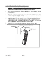
Page 6: ...Adaptor part 1 onto the Spindle See Figures B C and Assy Diagram 4 Then use the Spanner part 43 provided to keep the Adaptor part 1 from turning and firmly hand tighten the Wool Compounding Bonnet on...

Page 7: ...y Diagram 3 Firmly hand tighten the threaded portion of the Side Handle part 20 into the desired mounting hole of the Polisher Sander See Figure C and Assy Dia gram MOUNTING HOLE BRAKE PIN 18 MOUNTING...

Page 8: ...Rubber Backing Plate 46 onto the threaded end of the Spindle 3 until it is snug See diagram below 4 Ahere Sandpaper Disc not included evenly across the Rubber Backing Plate The Rubber Backing Plate h...

Page 9: ...eds from 1 000 RPM to up to 3 000 RPM depending on the material of the workpiece To change speeds make sure the Polisher Sander is off Then select the desired speed using the Variable Switch part 31 S...

Page 10: ...e Brush Caps See Figures B C and Assy Diagram 4 Do not use solvents to wipe off the Polisher Sander as damage may result If necessary wipe with a damp cloth You may use a mild detergent 5 Do not intro...

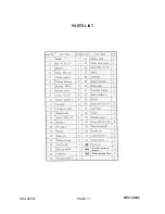
Page 11: ...SKU 46507 PAGE 11 PARTS LIST 1 Adaptor Rubber Backing Plate Wool Compounding Bonnet REV 09 02...

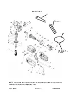
Page 12: ...me parts are listed and shown for illustration purposes only and are not available individually as replacement parts SKU 46507 PAGE 12 45 Note 45 includes Arbor Nut 5 8 11 TPI For Sanding 44 REV 09 02...

Reviews: