2
5
(Q-1001)
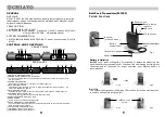
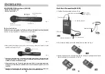
HAND-HELD Microphone
Fig. 1.
Fig. 2.
Fig. 3
Fig. 4
Fig. 6
Caution:
The audio cable serves as antenna for this VHF system. Please stretch the
cable to its maximum to get the most efficient transmission power.
6
Fig. 7
Fig. 8
Fig. 9
7.
Switch off the power then the
microphone is not in use, mean-
while, remove the battery out
of the microphone if it is not to
be used for an extended period.
As soon as the switch is on, the battery-status indicator will give a flash to indicate
a normal operation. If there is no flash, it indicates either power supply is not
available or battery is installed wrongly.
After switching on, the Therefore signal indicator LED(s) of matching transmitter
will light up to indicate the transmission of the microphone signal is in normal
operation.
Switch off the power when the microphone is not in use, meanwhile, remove the
battery out of the microphone if it is not to be used for an extended period.
4.
Sliding the power switch on the transmitter control panel to
"ON" position, as shown in Fig.7, the battery status indicator
gives a flash to indicate a normal operation. If there is no flash,
it indicates either power supply is not available or battery is
installed wrongly. If the indicator keeps lighting , it indicates
that battery is weak , a replacement is necessary.
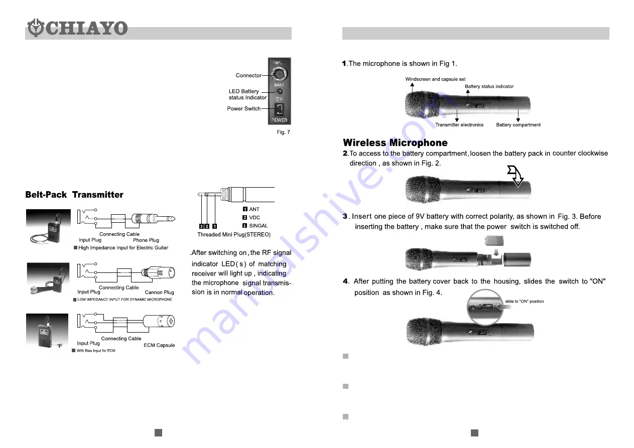
5.The pin arrangement of the transmitter's connector jack is
shown in Fig.6. A unique feature of the M-1001 is its separate
high/low impedance and bias with the same jack for ECM
input. You could properly match the high impedance input
signals such as electric guitar or low impedance input signals
such as dynamic microphone, then choose the proper input
connecting cable and plug correctly, as shown in Fig.7,8,9.


