


11
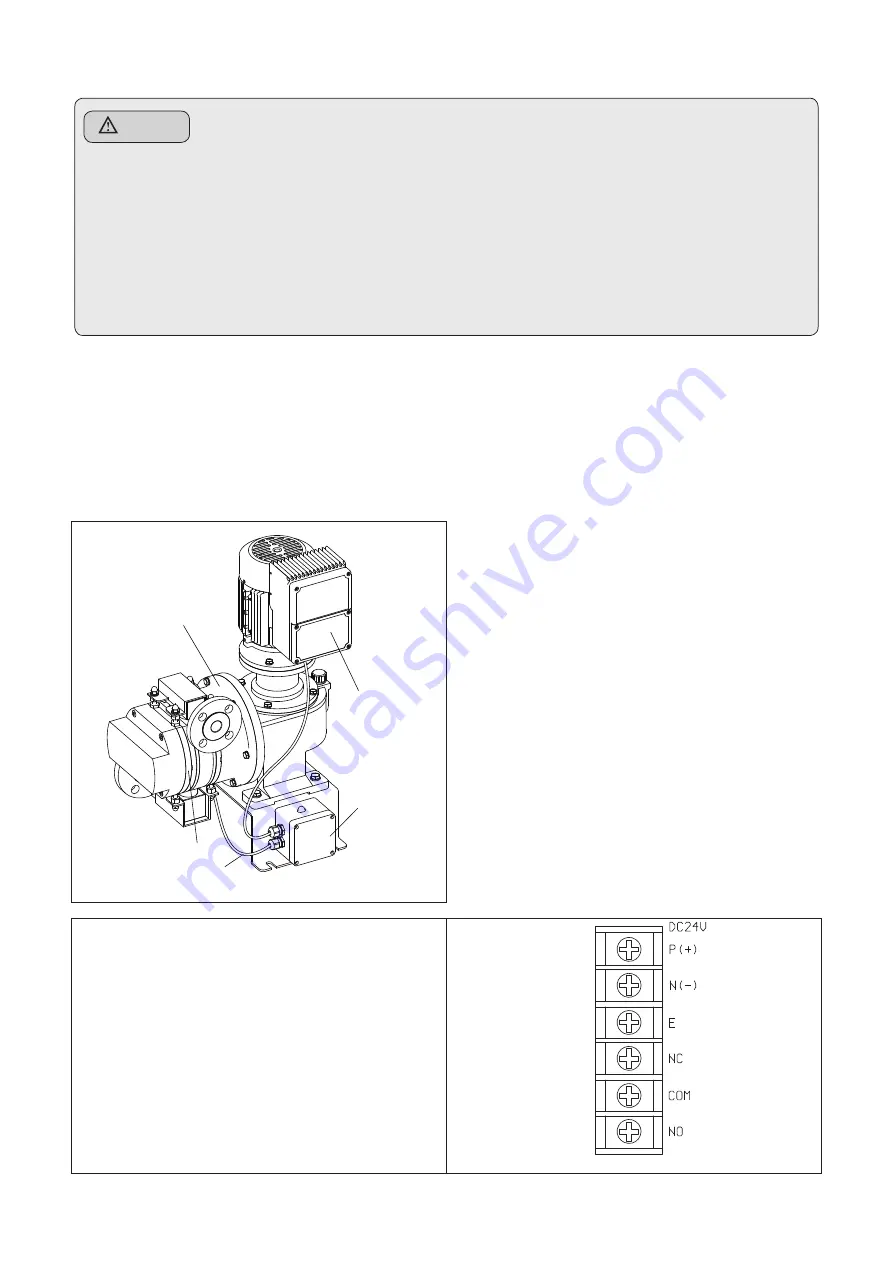
9-6 Diaphragm Damage Sensor
A detector sensing damage to the diaphragm is added to the PDS pump series, which is designed to
sense any damage to the diaphragm during pump operation and stop the pump to protect the pump
system. A sensor is mounted on the gear box flange and the front flange; when the diaphragm gets
damages, it senses fluid leaked at its back and sends a signal. This system is easy to install.
The BLDC M/C UNIT or a separate inverter receives the detection signal and brings the pump to a stop.
The diaphragm sensor and the BLDC driver
are wired at the factory before the product is
shipped.
The lamp gets lit when the sensor detects any
damage to the diaphragm. The operator can
monitor damage to the diaphragm using the
trip of the BLDC driver terminal block.
When an induction motor is used, the operator
can monitor the condition of the diaphragm
using the relay of the detector. Do wiring to the
terminal block of the detector in reference to
the following instruction.
Input Power : DC24V 300mA
Relay Spec. : SPDT 2A DC30V
Cable Standard : AWG18~26
Cable Connector Standard : PF 3/4″
P(+), N(-) : Input Power
E : Ground
NC, COM, NO : Relay
Caution
•
After checking the power specification of the BLDC M/C UNIT before wiring, connect the pump to the
rated power. If not, it may cause trouble and fire.
•
Pump should be properly grounded in order to prevent electric shock.
•
Entrust the wiring to electrical engineer.
•
Install regulated Magnet Switch and Thermal Relay for the adjustment and maintenance of the pump.
•
Use standardized parts in wiring and fully pay attention to safety in accordance with the technical
standard & wiring regulation of the electrical equipment.
•
Reverse rotation of the motor causes trouble, so wire the motor’s power so that the motor’s
rotation direction is clockwise.(This is only for Inverter and general motor.)
Front flange
Sensor Cable
Terminal
box
BLDC M/C
Unit
Gearbox
flange