background image

Page 9 

5.2 Common Controls Sidebar 

Figure 5.1 above shows the first page viewed when navigating to the webserver. The menu at the 
top  allows  the  user  to  choose  what  is  visible  in  the  central  window,  and  the  sidebar  shows 
information and has a select few commands that are useful regardless of the central page the user 
is on.The function of the controls on the sidebar is detailed in the subsequent table (Table 5.1) 


Control 

Function 

'RESET' button 

Resets the microDAQ, similar to power cycling the device.  Use to activate new 
settings and/or rebuild calibration tables. 

'Rezero' button 

Starts a microDAQ rezero operation. 

'Full Scale'  

Displays the value of the fullscale that the microDAQ is set up to use . 

'Channels' 

Displays the number of channels that the microDAQ is set up to use. 

‘Burn to eeprom” button 

Burns all changes made to the local settings into the eeprom 

Table 5.1, Common sidebar control functions. 

5.3.  The 'Setup' Page 
5.3.1 Introduction 

The  'Setup’  page  shows  all  of the  microDAQ's  main operating  parameters.    Setup  is  divided  into 
different categories by function, and each category is detailed separately in the following.  
 

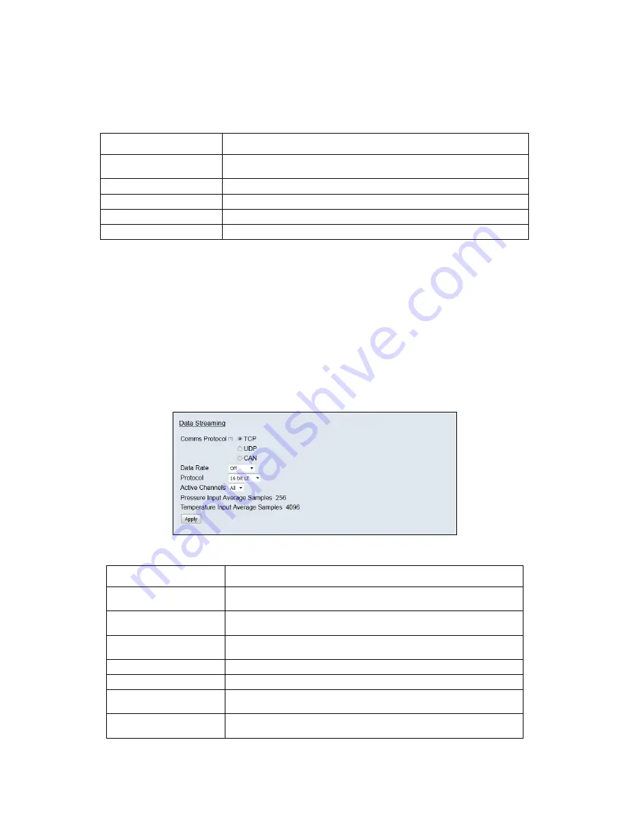
5.3.2 Data Streaming 

The ‘Data Streaming’ section allows the user to change settings that affect all three communication 
protocols,  and  allows  the  user  to  choose  the  protocol  that  is  to  be  used,  along  with  the  data 
transfer rate and the amount of channels. 


Figure 5.2, Data Streaming group 


Control 

Function 

‘Comms Protocol’ radio button 

Chooses the communication protocol that is to be used. When selected this button 
will change the communications page underneath to the appropriate comms menu. 

‘DATA Rate’ option list 

Selects the rate at which the microDAQ will transmit data, whether this value is for 
TCP, UDP  or CAN will depend on the comms protocol selection. 

‘Protocol’ option list 

Selects the format that the data will be transmitted as, options are 16 bit LE, 16 bit 
BE for all protocols and eng. units as an extra option for TCP and UDP Comms. 

‘Active channels’  

Selects the numbher of active channels, either 16,32,48 or All 

‘Apply’ button 

Applies the changes made to the local settings 

Pressure input Average 
Samples 

Standard moving averaging filter for the acquired pressure readings. 

Temperature input average 
samples 

Standard moving averaging filter for the acquired temperature readings. 

Table 5.2, Data Streaming settings. 

Summary of Contents for microDAQ-Mk2

Page 1: ...Road North Walsham Norfolk NR28 0AJ ENGLAND Tel 01692 500555 Fax 01692 500088 microDAQ Mk2 Pressure Scanner Acquisition System INSTALLATION AND OPERATING MANUAL e mail info chell co uk Visit the Chell...

Page 2: ...ied in this manual may impair the user s protection Chell Document No 900193 Issue 1 3 ECO 2230 Date 9th May 2016 Chell s policy of continuously updating and improving products means that this manual...

Page 3: ...erver 8 5 1 Introduction 8 5 2 Common Controls Sidebar 9 5 3 The Setup Page 9 5 3 1 Introduction 9 5 3 2 Data Streaming 9 5 3 3 TCP Parameters 10 5 3 4 UDP Parameters 10 5 3 5 CAN Parameters 11 5 4 Li...

Page 4: ...date both conventional HD series scanners and Digital Thermal Compensation DTC scanners with 16 32 and 64 channels The microDAQ is supplied with all the software required to configure it and read the...

Page 5: ...ons USB2 0 micro 57600 baud no parity 8 data bits and 1 stop bit 2 4 Ethernet Specifications TCP IP 10Mb s 100Mb s via Auto Negotiation TCP UDP protocols supported 2 5 Operating conditions Operating t...

Page 6: ...ge to the unit Always switch the power at the power supply source 3 3 Scanner Connector Internal micro miniature D type female Pin number Signal 1 Address line A0 2 Address line A1 3 Address line A2 4...

Page 7: ...atus If there isn t a valid connection the process waits until either a network is found or the timeout occurs This timeout is configurable via setup and ranges from 0 to 30 secs per check 2 checks Wh...

Page 8: ...d set and so on When the hardware trigger is activated the microDAQ will wait for the first pulse The time that this first pulse is generated can be measured by the user and therefore the time of the...

Page 9: ...s the tools for performing a new calibration namely calculating and downloading new coefficients and the means to managing calibration data Data from the calibration procedure and resulting coefficien...

Page 10: ...ach category is detailed separately in the following 5 3 2 Data Streaming The Data Streaming section allows the user to change settings that affect all three communication protocols and allows the use...

Page 11: ...ory Table 5 3 TCP Comms group settings 5 3 4 UDP Parameters The UDP section figure 5 5 holds all the settings specific to UDP In UDP mode each acquisition cycle of x number of channels is packed as a...

Page 12: ...whether an acknowledgement of these user commands is sent on the next higher message number Data may be transmitted on either multiple messages or alternatively on a single message ID with a selectab...

Page 13: ...16 bit unsigned calibrated decimal 16 bit unsigned and engineering units or voltage scaled to the known full scales Also for DTC scanners the temperature values as raw unsigned 16 bit and calibrated e...

Page 14: ...non temperature calibration may be performed at a single temperature Figure 5 9 shows the Calibration tab controls which are further explained in table 5 8 The Live values section is an indicator of...

Page 15: ...emperature calibration Unchecked only temperature point 1 is available to the user and the system will calculate coefficients for a non temperature calibration Live Values The live values of the curre...

Page 16: ...rol Function Range Shows the floating point value for the range contained within the scanner x3 derange Shows the floating point value for the sensitivity derange constant contained within the scanner...

Page 17: ...n data will remove single impulse noise events in the pressure data Temperature Input Impulse Filter As above but with temperature data Pressure input average samples Selects the number of samples for...

Page 18: ...TSEG1 TSEG2 SJW Register values for the CAN module within microDAQs microcontroller Table 5 9 Advanced communication settings 5 7 3 Miscellaneous The remaining parameters are edited via the Miscellan...

Page 19: ...AQ s internal calibration data table If I daq detected use raw calibration If checked this replaces the normal polynomial calibration function with a raw linear function whenever an I daq is present i...

Page 20: ...ear calibration Figure 5 12 Span and zero coefficients 5 9 Timestamp page This page allows the user to edit the timestamp settings of the microDAQ This timestamp will alow the user to get millisecond...

Page 21: ...the timestamp for every channel It should be noted that the latter 2 options will reduce the maximum transmission speed datastream get PC time This button allows the user to get the timestamp from the...

Page 22: ...ual basis and Chell Instruments Ltd Provides a fully traceable facility for this purpose 6 3 Adjustment There are no user adjustments in the instrument The user is strictly forbidden from removing the...

Page 23: ...uter Gnd 7 3 Can Connector Mating connector 9 way dtype male Pin Number Designation 2 CAN_L 5 Gnd 7 CAN_H 4 N C 5 0V 7 4 Trigger Connector Mating connector 50 Ohm BNC Pin Number Designation Center TTL...

Reviews: